DRAW Reference Manual
Section Planes : Creating and Using Planes : Flat Plane (FPLA)
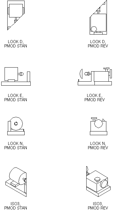
The NORM direction can be any standard direction, e.g. N45W, ISO2, or can be by reference to a Design element p-point, in which case the result will be stored as a 3D vector and the reference will be lost. Figure 5:5.: Use of the Flat Plane (FPLA) illustrates the use of a flat Plane, positioned at the pump coupling and with a NORM direction of N45W.
|
Figure 5:5.
|