Concrete Building Design
User Guide
Concrete Building Design : Sub-Components : Propose Sub-Component Without Write Access to the Owning Component
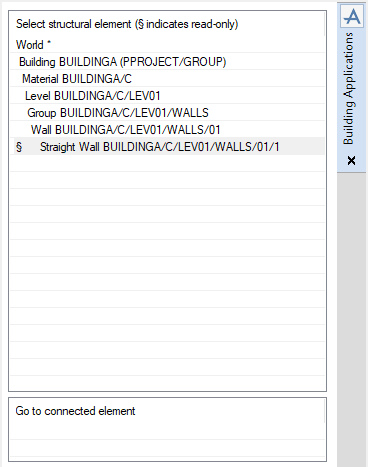
From the Select Structural Element pane of the Building Applications window, make sure that the sub-component is the CE.
On the Building tab, in the Create group, select the required sub-component in the Create Element drop-down list.
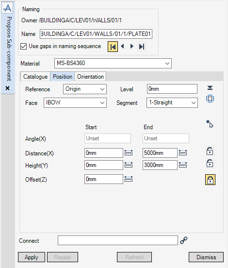
By default in the Naming pane of the Proposed Sub-component window, the application automatically populates the Name field with a name based on the project or company autonaming rules. For more information on the autonaming rules, refer to Naming for further information.
The Use gaps in naming sequence checkbox is also selected by default, the user can select which auto name is to be used. To select the:
|
•
|
first available name, click first available name.
|
|
•
|
previous available name, click previous available name.
|
|
•
|
next available name, click next available name.
|
|
•
|
last available name, click last available name.
|
The user can change the name which does not conform to the autonaming rules, to do this, type a new name into the Name field. If this name already exists, an Error window is displayed. If the name does not conform with the autonaming rules, Apply remains greyed out as long as the name is not properly entered.
The Material drop-down list by default is set according to the type of sub‑component, the material can be changed to another suitable material. From the Material drop-down list, the user can select from a list of suitable materials.
Choose the sub-component catalogue using the drop-down list in the Catalogue frame. The catalogue is activated by default on the first catalogue available that contains the type of component selected in the main window.
Read the question displayed between the two lists in the Catalogue frame. Select an answer in the list of answers displayed below until the Selection complete message appears. Click on the question in the list above to reselect a question.
As soon as an element in the catalogue is selected, Properties is cleared if there are properties associated with this element.
Click Properties to display the properties of the sub-component. Do not fill in the Angle or Offset properties as these are calculated automatically by the application.
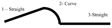
For a curved wall and a curved beam, choose the segment and the path using the Segment drop-down list. The type of each segment (straight or curved) is displayed in this list. For a straight wall, straight beam or column this list is greyed out.
|
•
|
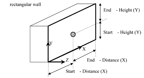
Enter the values in the Distance, Height and Offset fields. If the field is locked, click Distance/ Height/Offset Locked to unlock it.
|
|
•
|
Click Measure to measure the values of the distances. The Positioning Control window is displayed. The user is prompted to Start:Pick Start (Snap) Snap:, Start:Pick End (Snap) Snap:.The end position is adjusted to suit the new length.
|
|
•
|
Enter the values of the angles in the Angle (X) fields. The method is only available for curved segments. The distances in the X direction are adjusted.
|
|
•
|
Click Pick position to select the position in the graphical view. To avoid changing a desired value in a field, click Distance/ Height/Offset Unlocked to lock it. Click Grid to display a grid positioned in the proposed position and in the proposed direction.
|
|
•
|
Type the elevation of the sub-component in the Level field. The height value is adjusted to suit.
|
|
•
|
Click Pick Level to select the level in the graphical view. The Positioning Control window is displayed. Follow the prompt Pick Level (Snap) Snap:.The height value is adjusted to suit.
|
|
Note:
|
To position a sub-component on a face of a hole, select the closest face, unlock the Offset (Z) field and select the position in the graphical view using Pick Position.
|
|
•
|
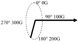
Enter the values in the Direction and Rotation fields. The direction is always shown with respect to the level. The angle can be indicated in the following forms:
|
|
•
|
Click Pick surface or edge to define direction to select the direction in the graphical view. Follow the prompt Pick Face or Edge. Select an object in the graphical view and drag the cursor to the desired face on edge. The direction is perpendicular to a face or along a line.
|
|
•
|
Enter the slope of the sub-component in the Slope field. The direction is adjusted to suit. The slope can be indicated in the following forms:
|
|
Note:
|
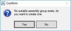
Click Apply to create the proposed sub-component. The proposed sub‑component is created under a suitable structure. The proposed sub-component has the name of the component followed by ‘(proposed)’. If no suitable structure is available the following message is displayed:
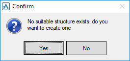
Click Yes to create a structure for the current building.
The Sub-component Modification window replaces the Proposed Sub-component window. Enter a valid name in the Name field to activate it.