DRAW
User Guide
Create and Modify Views : Format 2D View : Modify View with User-Defined View
The User-Defined View window allows the user to configure a selected view.
Select a view, on the Format 2D tab, in the Modify group, click Limits Defined and select User Defined from the drop-down list to display the User-Defined View window.
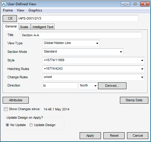
The User-Defined View window has similar functionality to the Limits-Defined View window. Refer to Create and Modify Views for further information.
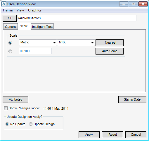
The Scale tab allows the user to set the scale of the view.
|
Select Metric from the drop-down list to scale the view using metric values. For example, 1/1.
Select Architectural from the drop-down list to scale the drawing using architectural values. For example, 1 1/2" = 1' -0".
Select Engineering from the drop-down list to scale the drawing using engineering values. For example, 1" = 10' -0".
|
|
|
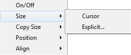
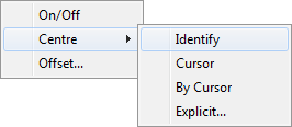
Allows the user to identify corner points for the view frame. Refer to Define View Frame with Cursor for further information.
|
|
|
Allows the user to set the frame size by specifying a ratio or coordinates. Refer to Explicit Frame Size for further information.
|
|
The user is prompted to Select element.
|
|
|
The user is prompted to Select element.
|
|
|
The user is prompted to Select element.
|
|
The user is prompted to Select element.
|
|
|
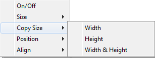
Allows the user to offset the design graphics. Refer to Design Graphics Offset for further information.
|
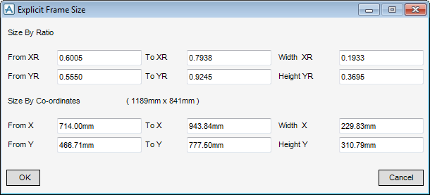
To size a frame explicitly on the drawing canvas, on the User-Defined View window, click Frame, select Size from the drop-down menu and select Explicit to display the Explicit Frame Position window.
|
The Width XR field is automatically updated based on information entered in the From XR and To XR fields. Modifying the Width XR field alters the From XR and To XR fields.
|
|
|
The Height YR field is automatically updated based on information entered in the From YR and To YR fields. Modifying the Height YR field alters the From YR and To YR fields.
|
|
|
Input a dimensional value in the field to specify the width between the From X and To X coordinates.
The Width X field is automatically updated based on information entered in the From X and To X fields. Modifying the Width X field alters the From X and To X fields.
|
|
|
Input a dimensional value in the field to specify the width between the From Y and To Y coordinates.
The Height Y field is automatically updated based on information entered in the From Y and To Y fields. Modifying the Height X field alters the From Y and To Y fields.
|
Click OK to apply the size settings or Cancel to discard any changes and close the Explicit Frame Size window. The user is returned to the User-Defined View window.
To define the centre position of a view on the drawing canvas, on the User-Defined View window, click View, select Centre from the drop-down menu and select Explicit to display the User Defined Centre Position window.
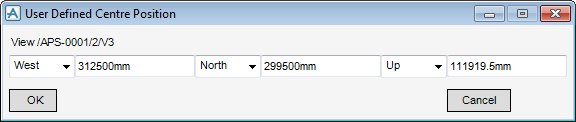
The direction can be defined in East, West, North, South, Up and Down directions using the drop-down lists.
Click OK to apply the centre position settings or Cancel to discard any changes and close the User Defined Centre Position window. The user is returned to the User-Defined View window.
To define the offset position of the design graphics on the drawing canvas, on the User-Defined View window, click View, select Offset from the drop-down menu to display the Design Graphics Offset window.
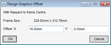
Click OK to apply the centre position settings or Cancel to discard any changes and close the Design Graphics Offset window. The user is returned to the User-Defined View window.