DRAW
User Guide
Create and Modify Views : Format 2D View : Modify View with Limits-Defined View
|
Note:
|
2D drawing sheets can be populated using the 3D view of the 3D model within DRAW. Refer to The 3D View for further information.
|
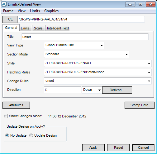
Select a view, on the Format 2D tab, in the Modify group, click Limits Defined and select Limits Defined from the drop-down list to display the Limits-Defined View window.
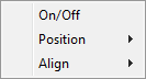
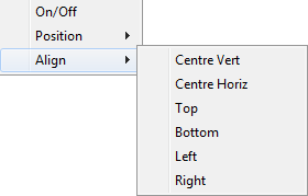
The Frame drop-down menu allows the user to define the frame visibility, position and alignment.
|
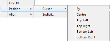
Allows the user to define the frame position using a cursor pick in the view. Refer to Define View Frame with Cursor for further information.
|
|||||||
|
Allows the user to position the frame explicitly on the drawing canvas. Refer to Explicit Frame Position for further information.
|
|
The user is prompted to Select element
|
|
|
The user is prompted to Select element
|
|
|
The user is prompted to Select element
|
|
|
The user is prompted to Select element
|
|
|
The user is prompted to Select element
|
|
|
The user is prompted to Select element
|
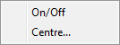
The View drop-down menu allows the user to define view visibility and centre position.
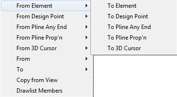
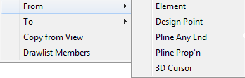
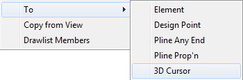
The Limits drop-down menu allows the user to define the limits of the view.
|
The user is prompted to Select element
|
|
|
The user is prompted to Select P-point
|
|
|
The user is prompted to Select P-Line end point.
|
|
|
The user is prompted to Select P-Line point.
|
|
|
Select from the drop-down menu to define a view limit from a point on the drawing, using a cursor pick in the view. Refer to Define View Frame with Cursor for further information.
The user is prompted to Specify position
|
|
The user is prompted to Select element
|
|
|
The user is prompted to Select P-point
|
|
|
The user is prompted to Select P-Line end point
|
|
|
The user is prompted to Select P-Line point
|
|
|
Select from the drop-down menu to define the view limit to a point on the drawing, using a cursor pick in the view.Refer to Define View Frame with Cursor for further information.
The user is prompted to Specify position
|
|
|
The user is prompted to Select element
|
|
The Graphics drop-down menu allows the user to modify the list of elements in the drawlist of a view.
|
Allows the user to apply a different drawlist to the view. Refer to Define View Contents for further information.
|
The General tab allows the user to apply various settings to define the view.
|
Select Universal Hidden Line from the drop-down list to create a Universal Hidden Line view.
Select Global Hidden Line from the drop-down list to create a Global Hidden Line view.
Select Local Hidden Line from the drop-down list to create a Local Hidden Line view.
Select Modelled Wireline from the drop-down list to create a Modelled Wireline view.
Select Wireline Hidden Line View from the drop-down list to create Wireline Hidden Line View.
Select Wireline from the drop-down list to create a Wireline view.
|
|||
|
Select Standard from the drop-down list to display all components in the view.
Select Omit Fractional Pipe Components from the drop-down list to remove any piping components that are partly displayed in the view.
|
|||
|
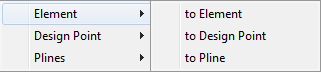
Allows the user to define the direction of the view from an element or design point. Refer to Direction for further information.
|
|||
|
|||
|
Allows the user to define attributes for the view. Refer to Limits-Defined View Attributes for further information.
|
|||
Click Apply to define the settings or Reset to revert to the values applied when the Limits-Defined View window was opened.
To define the view of piping insulation, on the General tab of the User Defined View window, select a style from the Style drop-down list.
|
Note:
|
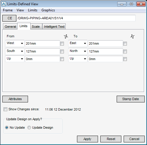
The Limits tab allows the user to set the limits of the view.
|
Input dimensional values in the From direction fields to define the limits of the view explicitly.
The direction can be defined in East, West, North, South, Up and Down directions using the drop-down lists.
|
|
|
Input dimensional values in the To direction fields to define the limits of the view explicitly.
The direction can be defined in East, West, North, South, Up and Down directions using the drop-down lists.
|
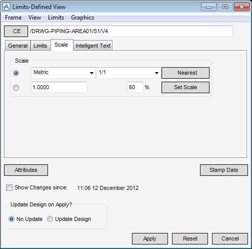
The Scale tab allows the user to set the scale of the view.
|
Select Metric from the drop-down list to scale the view using metric vales. For example, 1/1.
Select Architectural from the drop-down list to scale the drawing using architectural values. For example, 1 1/2" = 1' -0".
Select Engineering from the drop-down list to scale the drawing using engineering values. For example, 1" = 10' -0".
|
|
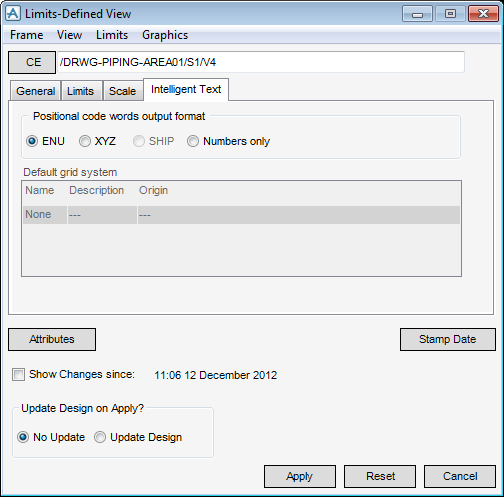
The Intelligent Text tab allows the user to set the output format of the positional code words, used to request the position of certain elements.
To define a direction for the view from an element, on the Limits-Defined View window, select the General tab, click Derived.
The user is prompted to Identify Design element for Derived Direction
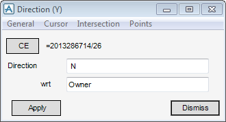
Select an element to display the Direction (Y) window.
|
Input a value in the field to modify the view direction. For example, input N to define a North direction.
|
|
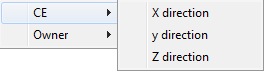
The General drop-down menu allows the user to define the view direction from the CE or the owning element of the CE in the hierarchy.
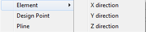
The Cursor drop-down menu allows the user to define the view direction from an element, design point or Pline.
|
The user is prompted to Identify Element
|
|
|
The user is prompted to Identify Element
|
|
|
The user is prompted to Identify Element
|
|
|
The user is prompted to Identify Design Point
|
|
|
The user is prompted to Identify Pline
|
The Intersection drop-down menu allows the user to define the view direction from two items using a cursor pick.
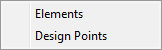
The Points drop-down menu allows the user to select three elements or design points on the drawing canvas to define the direction.
Click Apply to set the defined direction or Dismiss to discard any changes and close the Direction (Y) window. The user is returned to the Limits-Defined View window
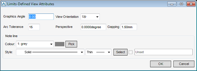
To modify Limits-Defined view attributes, on the Limits-Defined View window, click Attributes to display the Limits-Defined View Attributes window.
|
Input an angular value in the field to define the perspective angle. A value of 0 indicates a parallel view.
|
|
|
Alternatively, click Pick to display the Pick a colour window. The functionality of the Pick a colour window is explained, refer to Colour for further information.
|
|
|
Alternatively, click Select to display the User-defined linear styles window. Refer to User-Defined Linear Styles for further information.
|
Click OK to apply the attribute settings or Cancel to discard any changes and close the Limits-Defined View Attributes window. The user is returned to the Limits-Defined View window.
To position a frame explicitly on the drawing canvas, on the Limits-Defined View window, click Frame, select Position from the drop-down menu and select Explicit to display the Explicit Frame Position window.
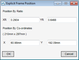
Click OK to apply the position settings or Cancel to discard any changes and close the Explicit Frame Position window. The user is returned to the Limits-Defined View window.
To define the centre position of a view on the drawing canvas, on the Limits-Defined View window, click View, select Centre drop-down menu to display the Design Centre Position window.
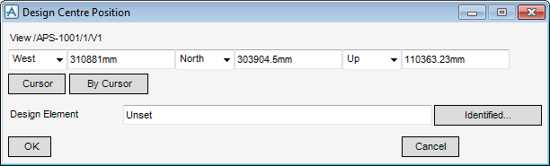
|
The direction can be defined in East, West, North, South, Up and Down directions using the drop-down lists.
|
|
|
The user is prompted to Select element
|
Click OK to apply the centre position settings or Cancel to discard any changes and close the Design Centre Position window. The user is returned to the Limits-Defined View window.