DRAW
User Guide
Create and Modify Views : Create Views : Create Vsec View
|
•
|
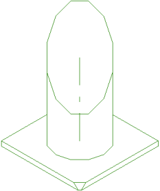
To create a stepped section plane, select an existing view, on the Format 2D tab, in the View group, click Section Plane.
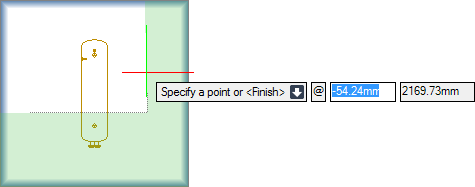
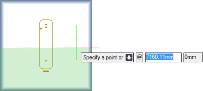
The user is prompted to Specify a point or
Input values in the dimension fields and press Enter or click to identify the cutting plane position.
The user is then prompted to Specify a point or
Move the cursor across the view, the shaded area indicates the area to be removed. Input values in the dimension fields and press Enter or click to identify the cutting plane position.
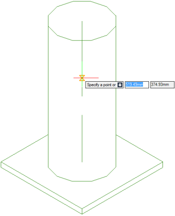
The user is again prompted to Specify a point or
Input values in the dimension fields and press Enter or click to identify the cutting plane position.
The user is then prompted to Specify a point or <Finish>
Input F at the prompt and press Enter to end the command. The stepped section plane is created and displays in the view.
Throughout the view creation process the user can press ESC to cancel the command. Additional functionality is also available.
 |
|
|
Press the down arrow key and select Finish to end the command.
|
|
|
Press the down arrow key and select Flat to create a Flat Vsec View. Refer to Create Flat Vsec View for further information.
|
|
|
Press the down arrow key and select clOse to return to the Specify cutting plane position or prompt. The user can click appropriate points of the view to create a closed shaded area.
|
|
|
Press the down arrow key and select Open to resume selection of the shaded area by moving the cursor across the view.
|
|
|
Press the down arrow key and select Perpendicular to create a Perpendicular Vsec view. Refer to Create Perpendicular Vsec View for further information.
|
|
|
Press the down arrow key and select Previous to identify a different location for the cutting plane position.
|
|
|
Press the down arrow key and select Side to invert an area of the shaded view.
|
|
|
Press the down arrow key and select View to create a Vsec view. Refer to Create Vsec View for further information.
|
|
To create a perpendicular Vsec view, select an existing view, on the Format 2D tab, in the View group, click Section Plane.
The user is prompted to Specify a point or
The user is then prompted to Specify a point or
Input values in the dimension fields and press Enter or click to identify the location of the perpendicular view.
Throughout the view creation process the user can press ESC to cancel the command. Additional functionality is also available.
 |
|
|
Press the down arrow key and select Flat to create a Flat Vsec View. Refer to Create Flat Vsec View for further information.
|
|
|
Press the down arrow key and select Stepped to create a stepped section view. Refer to Create Stepped Section View for further information.
|
|
|
Press the down arrow key and select View to create a Vsec view. Refer to Create Vsec View for further information.
|
|
To create a flat Vsec view, select an existing view, on the Format 2D tab, in the View group, click Section Plane.
The user is prompted to Specify a point or
The user is then prompted to Specify a point
Input values in the dimension fields and press Enter or click to identify the first point to define the excluded area. The shaded area indicates the area to be removed from the view.
The user is again prompted to Specify a point
Input values in the dimension fields and press Enter or click to identify the second point to define the excluded area. The command ends automatically and the shaded area is removed from the view.
Throughout the view creation process the user can press ESC to cancel the command. Additional functionality is also available.
 |
|
|
Press the down arrow key and select Angle to specify an angle to define the area to be removed from the view.
|
|
|
Press the down arrow key and select vErtical to define a vertical area to be removed from the view.
|
|
|
Press the down arrow key and select Finish to end the command.
|
|
|
Press the down arrow key and select Horizontal to define a horizontal area to be removed from the view.
|
|
|
Press the down arrow key and select Perpendicular to create a Perpendicular Vsec view. Refer to Create Perpendicular Vsec View view for further information.
|
|
|
Press the down arrow key and select Previous to undo the last point specified.
|
|
|
Press the down arrow key and select Side to invert an area of the shaded view.
|
|
|
Press the down arrow key and select Stepped to create a stepped section view. Refer to Create Stepped Section View for further information.
|
|
|
Press the down arrow key and select View to create a Vsec view. Refer to Create Vsec View for further information.
|
|
To create a Vsec view, select an existing view, on the Format 2D tab, in the View group, click Section Plane.
The user is prompted to Specify a point or
The user is then prompted to Specify projection
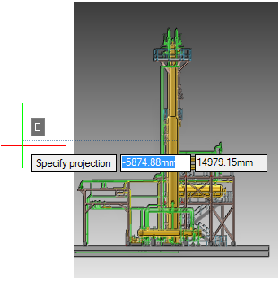
The user is then prompted to Specify a point or
Input values in the dimension fields and press Enter or click to identify the location of the cutting plane position.
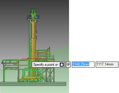
The user is again prompted to Specify a point or
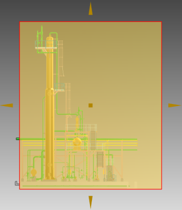
Input values in the dimension fields and press Enter or click to identify the cutting plane position. The shaded area indicates the area to be removed.
The user is then prompted to Specify a point or <Finish>
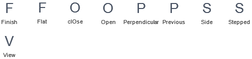
Throughout the view creation process the user can press ESC to cancel the command. Additional functionality is also available.
 |
|
|
Press the down arrow key and select Finish to end the command.
|
|
|
Press the down arrow key and select Flat to create a Flat Vsec View. Refer to Create Flat Vsec View for further information.
|
|
|
Press the down arrow key and select clOse to create a closed shaded area
|
|
|
Press the down arrow key and select Open to resume selection of the shaded area by moving the cursor across the view.
|
|
|
Press the down arrow key and select Perpendicular to create a Perpendicular Vsec view. Refer to Create Perpendicular Vsec View view for further information.
|
|
|
Press the down arrow key and select Previous to undo the last point specified.
|
|
|
Press the down arrow key and select Side to invert an area of the shaded view.
|
|
|
Press the down arrow key and select Stepped to create a stepped section view. Refer to Create Stepped Section View for further information.
|
|
To use the Format 3D tab to create a Vsec, select an existing view, on the Format 2D tab, in the Modify group, click Edit in 3D.
To define the limits of the view, on the Format 3D tab, in the Define limits group, click Limits from Drawlist (refer to The 3D View and Define Limits for further information).
On the Format 3D tab, in the Define Limits group, select the check box that corresponds to the view limits that form the Vsec.
The user is prompted to Modify view or <Finish>
If required modify the view. Refer to Format 3D Tab for further information.