DRAW
User Guide
Create and Modify Views : Create Views : Create Design View
To create a 3D view of the design with specified corners, on the Home tab, in the View group, click Design.
The user is prompted to Specify the first corner or
Input values in the dimension fields and press Enter or click to identify the first corner of the view.
The user is then prompted to Specify the opposite corner
Input values in the dimension fields and press Enter or click to identify the opposite corner of the view.
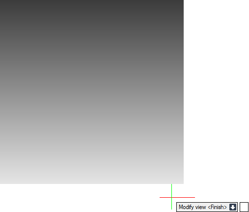
The user is then prompted to Modify view or <Finish>
Input F at the prompt and press Enter to end the command. The view is created and displays in 3D view mode.
Throughout the view creation process the user can press ESC to cancel the command. Additional functionality is also available.
 |
|
|
Press the down arrow key and select Centre to create a design view with a specified centre point. Refer to Create Design View with Specified Centre Point for further information.
|
|
|
Press the down arrow key and select Finish to end the command.
|
|
Add elements to the view as required. Refer to Add and Remove Model Items to/from the 3D View for further information. The Format 3D tab can also be used to further modify the view. Refer to Format 3D Tab for further information.
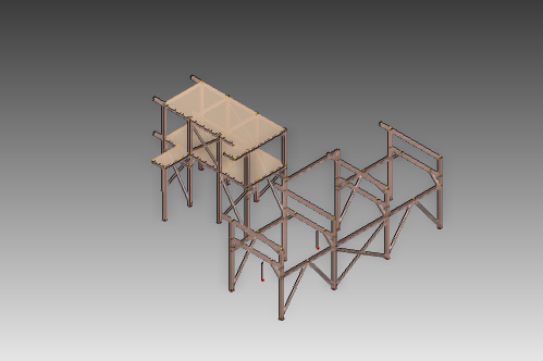
Press Enter when the view is complete.
To create a 3D view of the design with a specified centre point, on the Home tab, in the View group, click Design.
The user is prompted to Specify the first corner or
The user is then prompted to Specify centre point or
Input values in the dimension fields and press Enter or click to identify the centre of the view.
The user is then prompted to Specify the width
Input a dimensional value in the field and press Enter or move the cursor left or right to define the width of the view. Click to confirm the required width.
The user is then prompted to Specify the height
Input a dimensional value in the field and press Enter or move the cursor up or down to define the height of the view. Click to confirm the required height. The view is created.
The user is then prompted to Modify view or <Finish>
Input F at the prompt and press Enter to end the command. The view is created and displays in 3D view mode.
Throughout the view creation process the user can press ESC to cancel the command. Additional functionality is also available.
 |
|
|
Press the down arrow key and select Corner to create a design view with specified corners. Refer to Create Design View with Specified Corners for further information.
|
|
|
Press the down arrow key and select Finish to end the command.
|
|
Add elements to the view as required. Refer to Add and Remove Model Items to/from the 3D View for further information. The Format 3D tab can also be used to further modify the view. Refer to Format 3D Tab for further information.