Equipment
User Guide
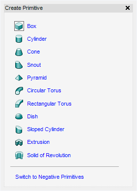
To create a primitive, on the Equipment tab, in the Create group, click Primitives to display the Create Primitive window.
|
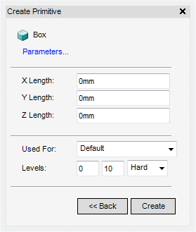
The Create Primitive window displays the parameters fields for a Box. Refer to Box Parameters for further information.
|
|
|
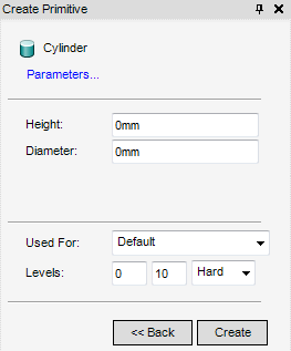
The Create Primitive window displays the parameters fields for a Cylinder. Refer to Cylinder Parameters for further information.
|
|
|
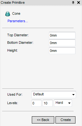
The Create Primitive window displays the parameters fields for a Cone. Refer to Cone Parameters for further information.
|
|
|
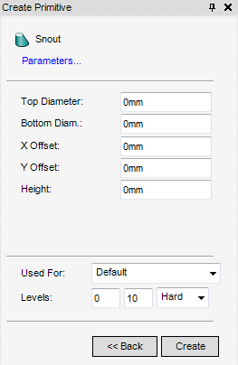
The Create Primitive window displays the parameters fields for a Snout. Refer to Snout Parameters for further information.
|
|
|
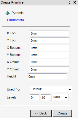
The Create Primitive window displays the parameters fields for a Pyramid. Refer to Pyramid Parameters for further information.
|
|
|
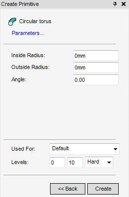
The Create Primitive window displays the parameters fields for a Circular Torus. Refer to Circular Torus Parameters for further information.
|
|
|
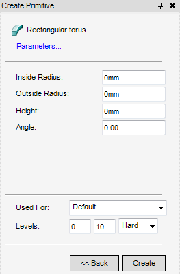
The Create Primitive window displays the parameters fields for a Rectangular Torus. Refer to Rectangular Torus Parameters for further information.
|
|
|
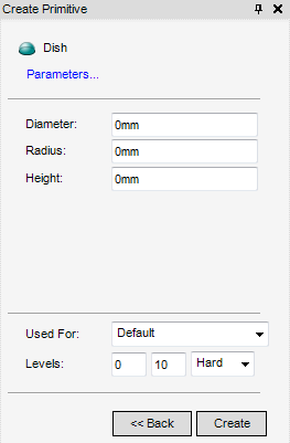
The Create Primitive window displays the parameters fields for a Dish. Refer to Dish Parameters for further information.
|
|
|
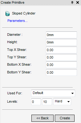
The Create Primitive window displays the parameters fields for a Sloped Cylinder. Refer to Sloped Cylinder Parameters for further information.
|
|
|
Displays the Create Negative Primitives window. Refer to Create Negative Primitive for further information.
|
After selecting the primitive to be created, the Create Primitive window displays the required parameters fields for the selected primitive.
|
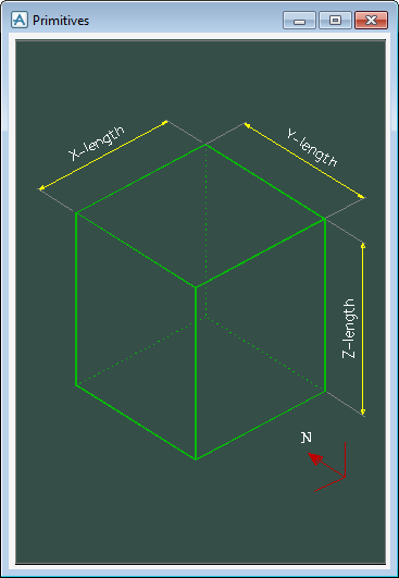
Displays the Primitives window, indicating the Parameters fields along the axis.
 |
|
Click Create to display the Box in the 3D view or Back to return to the select primitive part of the Create Primitive window. The Modify Primitive window displays by default.
|
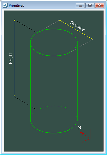
Displays the Primitives window, indicating the Parameters fields along the axis.
 |
|
Click Create to display the Cylinder in the 3D view or Back to return to the select primitive part of the Create Primitive window. The Modify Primitive window displays by default.
|
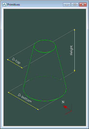
Displays the Primitives window, indicating the Parameters fields along the axis.
 |
|
Click Create to display the Cone in the 3D view or Back to return to the select primitive part of the Create Primitive window. The Modify Primitive window displays by default.
|
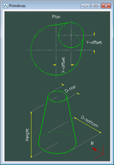
Displays the Primitives window, indicating the Parameters fields along the axis.
 |
|
Click Create to display the Snout in the 3D view or Back to return to the select primitive part of the Create Primitive window. The Modify Primitive window displays by default.
|
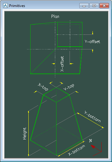
Displays the Primitives window, indicating the Parameters fields along the axis.
 |
|
Click Create to display the Pyramid in the 3D view or Back to return to the select primitive part of the Create Primitive window. The Modify Primitive window displays by default.
Select Circular Torus on the Create Primitive window to display the Parameters fields for a Circular Torus.
|
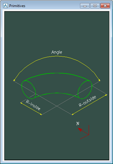
Displays the Primitives window, indicating the Parameters fields along the axis.
 |
|
Click Create to display the Circular Torus in the 3D view or Back to return to the select primitive part of the Create Primitive window. The Modify Primitive window displays by default.
Select Rectangular Torus on the Create Primitive window to display the Parameters fields for a Rectangular Torus.
|
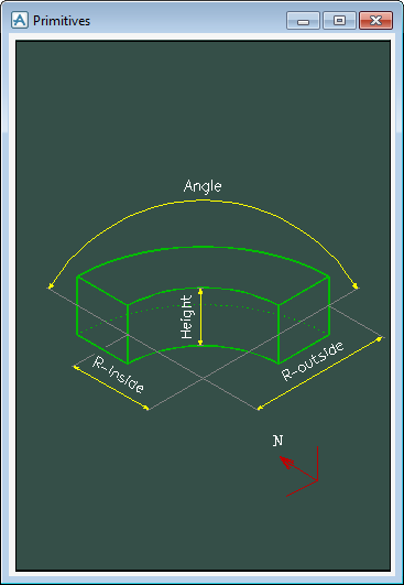
Displays the Primitives window, indicating the Parameters fields along the axis.
 |
|
Click Create to display the Rectangular Torus in the 3D view or Back to return to the select primitive part of the Create Primitive window. The Modify Primitive window displays by default.
|
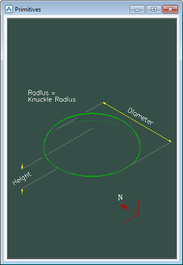
Displays the Primitives window, indicating the Parameters fields along the axis.
 |
|
Click Create to display the Dish in the 3D view or Back to return to the select primitive part of the Create Primitive window. The Modify Primitive window displays by default.
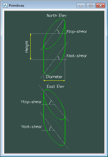
Select Sloped Cylinder on the Create Primitive window to display the Parameters fields for a Sloped Cylinder.
|
Displays the Primitives window, indicating the Parameters fields along the axis.
 |
|
Click Create to display the Sloped Cylinder in the 3D view or Back to return to the select primitive part of the Create Primitive window. The Modify Primitive window displays by default.
The Create an Extrusion window allows the user to create a set of extrusion vertices in various ways, depending on the requirements of the design. It also allows the user to set the other attributes necessary to relate these vertices to a 3D extrusion representation.
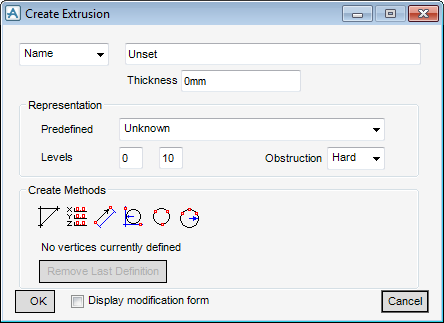
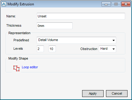
Select Name from the drop-down list and input an extrusion name in the Name field. Alternatively, select Autoname for the Equipment application to name the extrusion by default.
Input the extrusion thickness in the Thickness field
The Modify Representation part of the Create Extrusion window allows the user to select pre-defined settings that display the level of detail visible to the user. The levels visible in MODEL determine the display. The current visible levels are set by the Graphic Settings window. Refer to Graphics for further information.
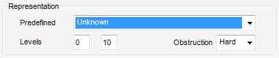
Select a level type from the Predefined drop-down list. As well as selecting a pre-defined level, the user can select Default or Unknown, from the Predefined drop-down list. The fields in the Levels drop-down list are populated by default.
Select an Obstruction value from the Obstruction drop-down list. The options are Hard, Soft or None.
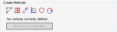
The Create Methods part of the Create Extrusion window allows the user to define the position of a new positive or negative extrusion vertex (VERT).
|
|
The user is prompted to Define vertex (Distance[0]) Snap :
The Positioning Control window displays by default. Refer to Positioning Control for further information.
|
|
|
The Positioning Control window displays by default. Refer to Positioning Control for further information.
|
|
|
Displays the Define vertex window. Refer to Define Vertex Offset from Previous for further information.
The Positioning Control window displays by default. Refer to Positioning Control for further information.
|
|
|
Displays the Radius window. Refer to Construct a Fillet Arc with Specified Radius between two Tangential Lines for further information.
|
|
|
The user is prompted to Extrusion arc (three points) first point (Distance[0]) Snap :
then Extrusion arc (three points) second point (Distance[0]) Snap :
|
|
|
The user is prompted to Extrusion arc (through 2 points) start point (Distance[0]) Snap :
then Extrusion arc (through 2 points) end point (Distance[0]) Snap :
|
Click Remove Previous Point to remove the most recently defined point or Remove Previous Arc to remove the most recently defined arc.
Select the Display Modification Form check box to display Loop editor on the Modify Extrusion window when the user applies an extrusion. Refer to Loop Vertex Editor for further information.
Click Apply to create the extrusion or Cancel to discard any changes and close the Modify Extrusion window.
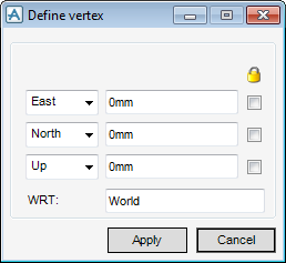
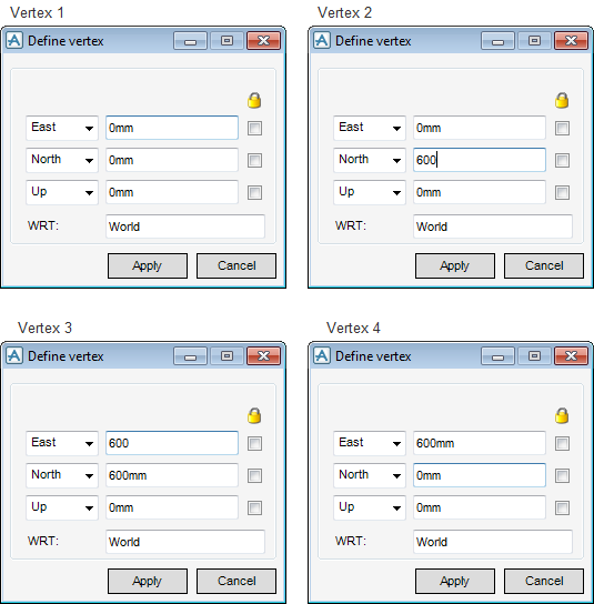
The Define vertex window allows each point to be explicitly positioned with respect to (WRT) another element.
|
From the drop down menu, click to identify the direction of the East/West axis. The user can then input an explicit position value in the Position field.
|
|
|
From the drop down menu, click to identify the direction of the North/South axis. The user can then input an explicit position value in the Position field.
|
|
|
From the drop down menu, click to identify the direction of the Up/Down axis. The user can then input an explicit position value in the Position field.
|
In the WRT text box, input the name of the element to which all co-ordinates are interpreted with respect to, the default is World.
Click Apply to create the point or Cancel to discard any inputs and close the Define vertex window. The user is returned to the Create Extrusion window.
The Define vertex window allows the user to specify a distance and direction which define a point relative to the position of the preceding vertex
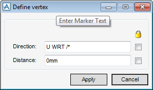
Input a value in the Direction field to define the direction of the point relative to the preceding vertex.
Input a value in the Distance field to define the distance of the point relative to the preceding vertex.
Click Apply to create the point or Cancel to discard any inputs and close the Define vertex window. The user is returned to the Create Extrusion window.
The user can construct a fillet arc with a specified radius between two picked tangential lines. The Radius window allows the user to define the required radius.
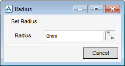
Input a value in the Radius field to define the radius of the fillet arc. Alternatively, Click  to pick two points whose separation defines the radius using a cursor pick in the 3D view. The user is prompted to Measure distance start (Distance[0]) Snap : then Measure distance end (Distance[0]) Snap :
Once the radius has been defined, the user can pick two lines between which the fillet arc is to be constructed using a cursor pick in the 3D view. The user is prompted Extrusion arc fillet First element : then Extrusion arc fillet Second element :
The user is returned to the Create Extrusion window.
Select the Display Modification Form check box to display Loop editor on the Modify Extrusion window when the user apples an extrusion.
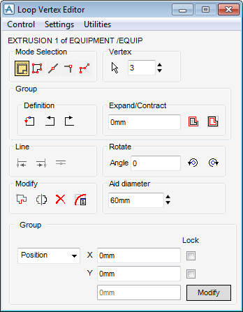
The Control part of the Loop Vertex Editor window allows the user to control the element to edit and close the window.
|
Click to discard any inputs and close the Loop Vertex Editor window.
|
The Settings part of the Loop Vertex Editor window allows the user to define the way in which the window is used.
|
When Confirm is selected the user must click Modify at the bottom of the window to implement each modification. When Confirm is not selected each modification is implemented immediately.
|
|
|
When Confirm is selected the user must confirm each deletion in order to complete the command. When Confirm is not selected deletions are implemented immediately.
|
|
|
When Tag edges is selected each edge is tagged with the number of the vertex at its start.
|
|
|
When Display Axes is selected the axes of the primitive are displayed at the first vertex in the 3D view.
|
|
|
When Free rotate is selected groups of vertices can be orientated by default when moved from one edge to another.
|
On the Loop Vertex Editor window, click Utilities, select Remove coincident from the drop-down list to remove two or more vertices that are at the same position.
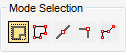
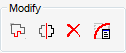
The Mode Selection part of the Loop Vertex Editor window allows the user to modify a single vertex, an edge or a group of vertices.
 .
.|
|
The Positioning Control window displays by default. Refer to Positioning Control for further information.
|
|
|
The user is prompted to Pick points, <escape> to select :
The Positioning Control window displays by default. Refer to Positioning Control for further information.
|
|
|
The user is prompted to Pick near edge :
The Positioning Control window displays by default. Refer to Positioning Control for further information.
|
|
|
The user is prompted to Pick screen position :
The Positioning Control window displays by default. Refer to Positioning Control for further information.
|
|
|
The user is prompted to Create new vertex(Distance[0]) Snap :
|
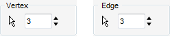
The Vertex/Edge part of the Loop Vertex Editor window allows the user to select a vertex or edge, depending on the current mode.
|
|
In vertex mode, the user is prompted to Pick screen position :
In edge mode, the user is prompted to Pick near edge :
The Positioning Control window displays by default. Refer to Positioning Control for further information.
|
|
|
The Vertex/Edge Counter displays the currently selected vertex/edge in the 3D view. The user can navigate to a specific vertex or edge by inputting the vertex/edge number in the text field. Alternatively, select the up/down arrows to step through the list.
The Positioning Control window displays by default. Refer to Positioning Control for further information.
|
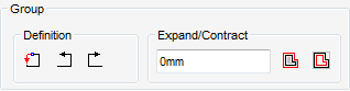
The Group part of the Loop Vertex Editor window allows the user to modify the currently selected group of vertices.
|
|
|
|
|
|
|
|
|
|
|
Moves each edge of the group outwards by the distance specified in the Expand/Contract text field normal to its own direction.
|
|
|
moves each edge of the group inwards by the distance specified in the Expand/Contract text field normal to its own direction.
|
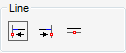
The Line part of the Loop Vertex Editor window allows the user to modify the currently selected edge.
|
|
Moves the Start vertex along the edge direction to align it through a picked position using a cursor pick in the 3D view.
The user is prompted to Pick point start is to be projected through :
Alternatively, if a line is selected, the End vertex is moved along the edge direction until it intersects the picked line. These operations can change the edge length.
|
|
|
Moves the End vertex along the edge direction to align it through a picked position using a cursor pick in the 3D view.
The user is prompted to Pick point end is to be projected through :
Alternatively, if a line is selected, the Start vertex is moved along the edge direction until it intersects the picked line. These operations can change the edge length.
|
|
|
The user is prompted to Pick line to be made parallel with :
|
|
|
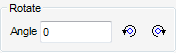
Rotates the edge anticlockwise, through the rotation angle specified in the Angle text field, about the reference end. The operation maintains the edge length.
|
|
|
Rotates the edge clockwise, through the rotation angle specified in the Angle text field, about the reference end. The operation maintains the edge length.
|
|
|
|
|
|
The Positioning Control window displays by default. Refer to Positioning Control for further information.
|
|
|
|
|
|
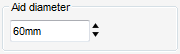
The Aid Diameter part of the Loop Vertex Editor window allows the user to control the size of the Aid spheres in the 3D view when modifying groups of vertices.
The Vertex/Edge/Group part of the Loop Vertex Editor displays co-ordinate data for the currently selected vertex, edge or group depending on the current mode.
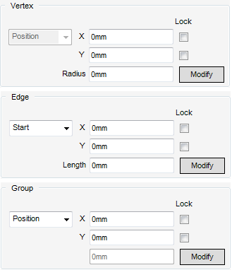
The user can modify the Start, End, Aligned, Extend Start and Extend End co-ordinates for a an edge using a selection from the drop-down list. If required, select one or all of the Lock check boxes to lock the explicit position of the current co-ordinate.
The user can modify the Position or Origin co-ordinates for a group using a selection from the drop-down list. If required, select one or all of the Lock check boxes to lock the explicit position of the current co-ordinate.
Click Modify to apply the modifications to the extrusion.
The Modify Arc window allows the user to define a fillet arc, manipulating a circle at the current vertex position.
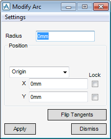
The Settings part of the Modify Arc window allows the user to specify default settings for the arc modification.
|
When Best Fit is selected, the Equipment application attempts to construct the circle which best fits between adjacent arcs or points by default. The circle has twice the minimum radius which just fits between the adjacent arcs.
|
Input a value in the Radius field to define the radius of the construction circle from which the panel shape is derived. Alternatively, select Radius from the Position drop-down list to pick a point through which the circle is to pass using a cursor pick in the 3D view.
Select Origin from the Position drop-down list and input values in the X/Y fields to set the centre of the circle. Alternatively the user can position the centre of the circle using a cursor pick in the 3D view.
Click Flip Tangents to change the tangents between adjacent construction circles to the opposite sides of the circles, where the geometry allows two valid configurations to exist.
Click Apply to modify the arc or Dismiss to discard any inputs and close the Modify Arc window. The user is returned to the Loop Vertex Editor window.
In the example below the user has selected to create the extrusion with explicit coordinates, the Define Vertex window appears. Click Apply to create the each vertex point.
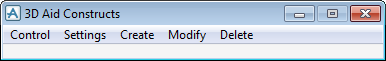
To create a constructional aid line, on the 3D View tab, in the Aids group, click Graphical Aids, select Constructs from the drop-down list to display the 3D Aid Constructs window.
On the 3D Aid Constructs window, click Create, select Line from the drop-down list, select Explicit from the drop-down list to display the Modify Line window.
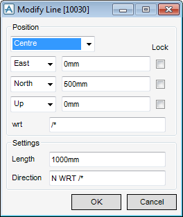
The Modify Line window allows the user to create and position a line. Refer to 3D Construction Aids for further information.
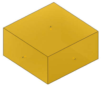
To create a revolution make sure the correct Primitive element is selected in the Model Explorer. On the Equipment tab, in the Create group, click Primitives to display the Create Primitive window.
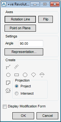
The +ve Revolution window allows the user to create the revolution by creating the rotation points.
On the +ve Revolution window, click Rotation Line, the user can select the constructional aid line using a cursor pick in the 3D view. The user is prompted to Pick line to rotate about : The constructional aid line is used as the start position for the rotational axis.
On the +ve Revolution window, click Point on Plane, the Positioning Control window displays by default. Refer to Positioning Control for further information.
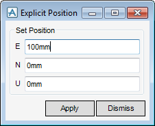
In the Set Position fields, input the explicit position of the plane in which the loop is defined (the start of the generated shape). Click Apply to create the position point or Dismiss to discard any inputs and close the Explicit Position window.
On the +ve Revolution window, click  to display the Positioning Control window. Refer to Positioning Control for further information.
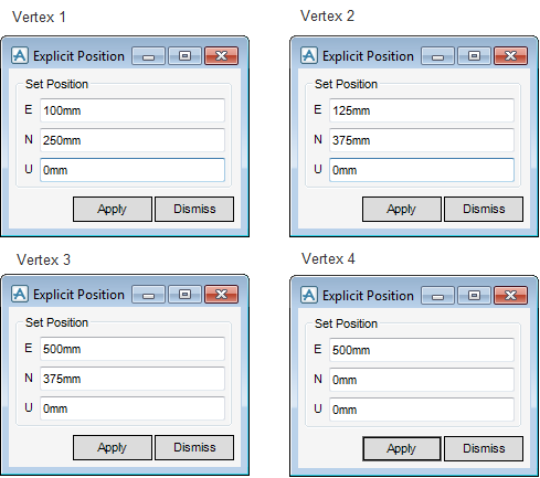
In the Set Position fields, input the explicit positions of each vertex. Click Apply each time the values are entered to create a new vertex or Dismiss to discard any inputs and close the Explicit Position window.
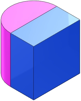
Once all the Vertex positions have been entered, click OK on the +ve Revolution window and the Revolution primitive is created.
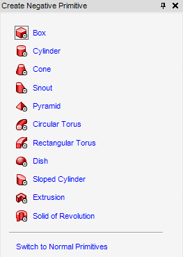
On the Create Primitive window, select Switch to Negative Primitives to display the Create Negative Primitive window.
|
The Create Negative Primitive window displays the parameters fields for a Box. Refer to Box Parameters for further information.
|
|
|
The Create Negative Primitive window displays the parameters fields for a Cylinder. Refer to Cylinder Parameters for further information.
|
|
|
The Create Negative Primitive window displays the parameters fields for a Cone. Refer to Cone Parameters for further information.
|
|
|
The Create Negative Primitive window displays the parameters fields for a Snout. Refer to Snout Parameters for further information.
|
|
|
The Create Negative Primitive window displays the parameters fields for a Pyramid. Refer to Pyramid Parameters for further information.
|
|
|
The Create Negative Primitive window displays the parameters fields for a Circular Torus. Refer to Circular Torus Parameters for further information.
|
|
|
The Create Negative Primitive window displays the parameters fields for a Rectangular Torus. Refer to Rectangular Torus Parameters for further information.
|
|
|
The Create Negative Primitive window displays the parameters fields for a Dish. Refer to Dish Parameters for further information.
|
|
|
The Create Negative Primitive window displays the parameters fields for a Sloped Cylinder. Refer to Sloped Cylinder Parameters for further information.
|
|
|
Displays the Create Negative Extrusion window. Refer to Create Negative Extrusion for further information.
|
|
The Create Negative Extrusion window allows the user to create a set of extrusion vertices in various ways, depending on the requirements of the design.
On the Create Negative Primitive window, select Extrusion to display the Create Negative Extrusion window.
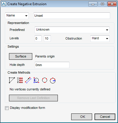
The functionality of the Create Negative Extrusion window is identical to the Create Extrusion window, with the exception of the Settings part of the window. Refer to Create Extrusion for further information.
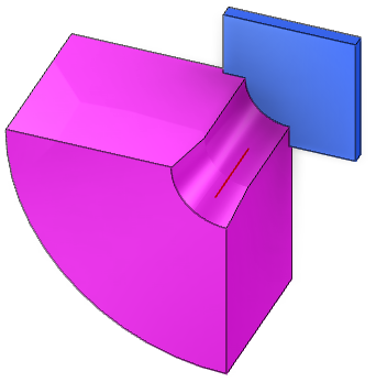
The settings part of the Create Negative Extrusion window allows the user to define the position and orientation of the hole.
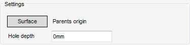
|
The user is prompted to Pick Surface to be used as datum :
|
|
Click Apply to create the negative extrusion or Cancel to discard any changes and close the Modify Negative Extrusion window.
On the Create Negative Primitive window, select Solid of Revolution to display the -ve Revolution window.
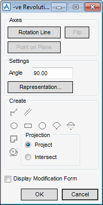
The functionality of the -ve Revolution window is identical to the +ve Revolution window. Refer to Create Revolution for further information.
To check the P-point position of a primitive, on the Home tab, in the Common group, click Attributes, select General from the drop-down list to display the Query window. The Query window allows the user to query current data settings. The functionality available from the Query window is common across all MODEL applications,. Refer to Query for further information.