DRAW Reference Manual
Dimensioning : Angular Dimensions
The simplest type of Angular Dimension (ADIM) consists of a pair of directions in the Design model (the dimension directions) that radiate out from the dimension origin. These directions are projected onto the drawing and are represented by projection lines. Between these lines a dimension arc is drawn centred upon the dimension origin. Each dimension arc and projection line may have a piece of text associated with it.
The dimension origin may either be defined explicitly by attributes of the ADIM or implicitly by the intersection of two dimension directions. These are illustrated by Figure 11:31.: Single Value Angular Dimension with origin defined in database and Figure 11:32.: Single Value Angular Dimension with origin defined by intersection.
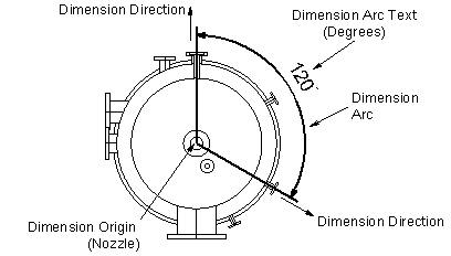
Figure 11:31.: Single Value Angular Dimension with origin defined in database shows an Angular Dimension with its origin defined as a Nozzle in the centre of the vessel. The two dimension directions are both defined as directions from the ADIM's origin to the origins of Nozzles. This Angular Dimension could be created by typing the following commands, starting at Layer level:
The ON command sets the DDNM attribute of the ADIM to the name of the Design element at the Dimension origin. The NPPT attribute of the ADIM is set to the nominated p-point. If none is defined (as in this example) NPPT will be set to a default value that equates to the origin of the element named by the DDNM.
In this example the Dimension Directions will be DPPT elements: these also have DDNM and NPPT attributes. In this case DDNM is set to the name of the Design element specified by the FROM or TO keyword, and NPPT to the nominated p-point (or the origin by default).
The DPOS @ command, which allows the position of the Dimension Arc to be defined, sets the DPOS attribute of the Angular Dimension. Alternatively the Arc radius could be defined by setting the Dimension's DOFF attribute. For convenience both these attributes can be set at members of the Angular Dimension. They are mutually exclusive: setting one will cause the other to be unset.
For the Angular Dimension shown in Figure 11:32.: Single Value Angular Dimension with origin defined by intersection the Q DESCription command will typically give:
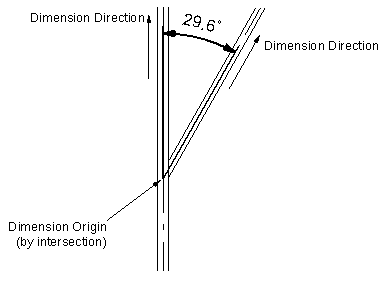
Figure 11:32.: Single Value Angular Dimension with origin defined by intersection shows an Angular Dimension with its origin defined implicitly by the intersection of the two Dimension directions, which are plines of SCTNs.. This Angular Dimension could be created by typing the following commands, starting at Layer level:
In this example the DDNM and NPPT attributes of the ADIM are left unset. The Dimension Directions will be APPT elements: these have DDNM, PPDI, and PKEY attributes. In this case DDNM is set to the name of the Design element specified by the FROM or TO keyword, and PPDI or PKEY to the nominated p-point or pline as appropriate. PPDI and PKEY are mutually exclusive: setting one will cause the other to be unset.
Plines and p-points define specific directions (eg UP) but in some cases when defining Angular Dimensions it is the 'reversed' direction that is required (eg DOWN). This can be achieved by the use of the REVDIR attribute of APPTs. By default this is False (or OFF) and the direction of the specified pline or p-point will not be reversed when drawing the Angular Dimension. If the reversed direction is required it should be set True (or ON).
For the Angular Dimension shown in Figure 11:32.: Single Value Angular Dimension with origin defined by intersection the Q DESCription command will typically give:
|
•
|
DPOI allows the direction to be defined by any given 3D position
|
|
•
|
ADIR allows the direction to be defined by any given 3D direction
|
Here the FROM and TO commands set the POS attribute of each DPOI to the position defined by the cursor.
The DIR attribute of each ADIR will be set to the specified direction.
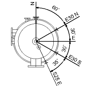
An example of a multi-valued chained Angular Dimension is shown in Figure 11:33.: Chained Angular Dimension.
|
Figure 11:33.
|
In this example the PLTX attribute of the ADIM is set to '#DIMDIR' and as a result the dimension directions appear as projection line text. #DIMDIR is an example of an intelligent text codeword. Refer to Intelligent Text for further information. #DIMDIR is valid in the PLTX of ADIM elements and their four potential member types.
For the Angular Dimension shown in Figure 12:34 the Q DESCription command will typically give:
|
Figure 11:34.
|
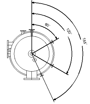
A parallel Dimension can be produced simply by setting the LCHA attribute of an ADIM to False (a chained dimension has LCHA True).