DRAW Reference Manual
Dimensioning : Linear Dimensions
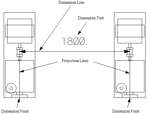
The simplest kind of Linear Dimension consists of a pair of points on a drawing, each of which relates to a point in the Design model. From each of these Dimension Points on the drawing, a projection line is drawn in a user-definable direction; between these parallel projection lines, dimension lines are drawn. Each dimension and projection line may have text associated with it. An illustration of a simple linear dimension between two Equipments is shown in Figure 11:2.: Single Value Linear Dimension.
|
Figure 11:2.
|
In the above example the Dimension Points will be DPPT elements - the Dimension Point is defined by a p-point of the Design element, in this case the origin. Any p-point can be nominated as a dimension point by replacing the FROM ID @ syntax above by FROM IDP @/TO IDP @. The Dimension may also be defined explicitly:
|
•
|
DPOI - allows you to dimension to/from any given 3D positions
|
|
•
|
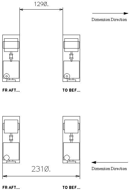
DPBA - allows you to dimension to/from ‘before’ or ‘after’ a Design element (in the Dimension direction).
|
The effect of such a command will depend upon the dimension direction. Refer to Principal Attributes of Angular Dimensions for further information. Figure 11:3.: Single Value ‘Before/After’ Linear Dimensions shows an example of such a linear dimension, produced by the same command but with different dimension directions.
Constructed points (refer to Point and Line Construction for further information) may also be used to create Dimension Points.
|
Note:
|
In cases where the dimension value is less than 0.01 mm, the display of all dimension point graphics (refer to Figure 11:2.: Single Value Linear Dimension for further information) will be suppressed.
|
When dimensioning BEFORE or AFTER elements such as EQUI, STRU or SUBS, DRAW will ignore those primitives with OBST (obstruction level) set to 0 or 1. When dimensioning BEFORE or AFTER a primitive, its OBST value will be ignored.
|
Figure 11:3.
|
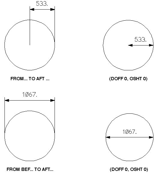
Figure 11:4.: Before/After’ Linear Dimensions on a Single Element shows examples of using ‘before/after’ linear Dimensions with a single element. (Refer to Principal Attributes of Linear Dimensions for further information about DOFF and OSHT.)
|
Figure 11:4.
|
|
Note:
|
Use of Radial Dimensions would provide a simpler method of drawing the two dimensions shown on the right-hand side of Figure 11:4.: Before/After’ Linear Dimensions on a Single Element. Refer to Radial Dimensions for further information.
|
Each FROM command sets the Dimension Point’s DDNM (Design Data Name) attribute to the Name of the Design element. The DDNM attribute may be reset immediately to define a new Dimension Point. If the DDNM is set to refer to an element, which is not in the Id List referenced from the current VIEW, the Dimension will still be drawn.
Reference checking is also available for Labels. Refer to Labelling for further information.
It is possible to draw a Dimension that contains Dimension Points that are incompletely defined (for example, a DPPT with an unset/illegal DDNM). The Dimension is now treated as only containing the significant Dimension Points for both drawing the Dimension and for commands which rely on the drawn dimension (such as PLCL @ (refer to Figure 11:8.: Key Attributes of a Linear Dimension for further information) and DTOF @ (refer to Detail Attributes of Linear Dimensions for further information).