Common Functionality
User Guide
Laser : Example Showing the Use of a Laser Survey in Pipe Modelling

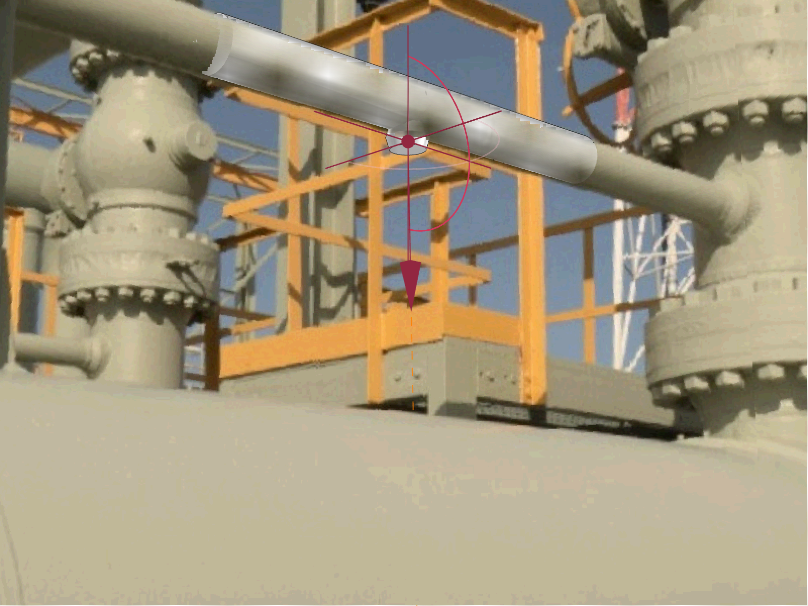
On the Laser tab, in the Tools group, clicking Fit Aid to Pipe allows the user to create temporary graphics to capture the part of the laser data to be modelled. The user is prompted to pick a pipe in the 3D View.

On the Laser tab, in the Tools group, clicking Trim Aid Pipe allows the user to adjust the temporary graphics to the required length.

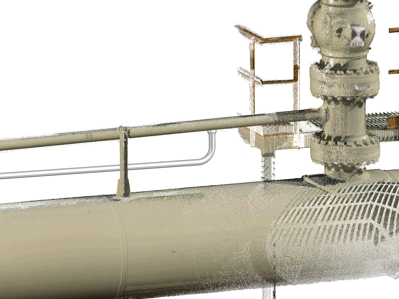
The temporary aid graphics are then converted to design points using the Aid to D-Points tool. This creates persistent elements within the database that are associated with the laser survey. These design points can then be used for a variety of purposes. In this case they are used to define the head and tail of the branch and complete the definition of the branch.
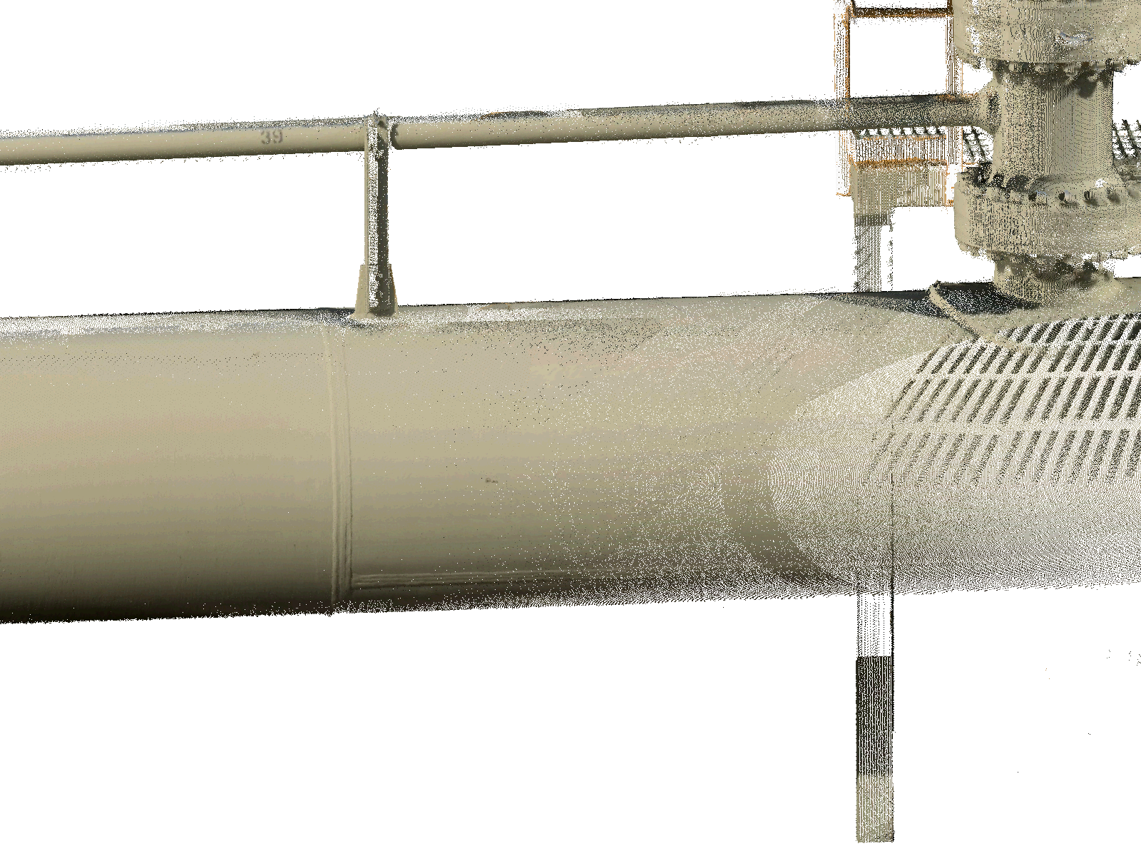
Using the Snap Head to D-Point and Snap Tail to D-Point the engineer can define a short section of piping from which to model from the laser survey.

Using the Piping Component Editor within the Piping application the user can create a threaded OLET on the modelled pipework. Refer to Component Creation for further information. The position and orientation of the OLET can fine tuned using the model editor. Refer to Model Editor for further information.
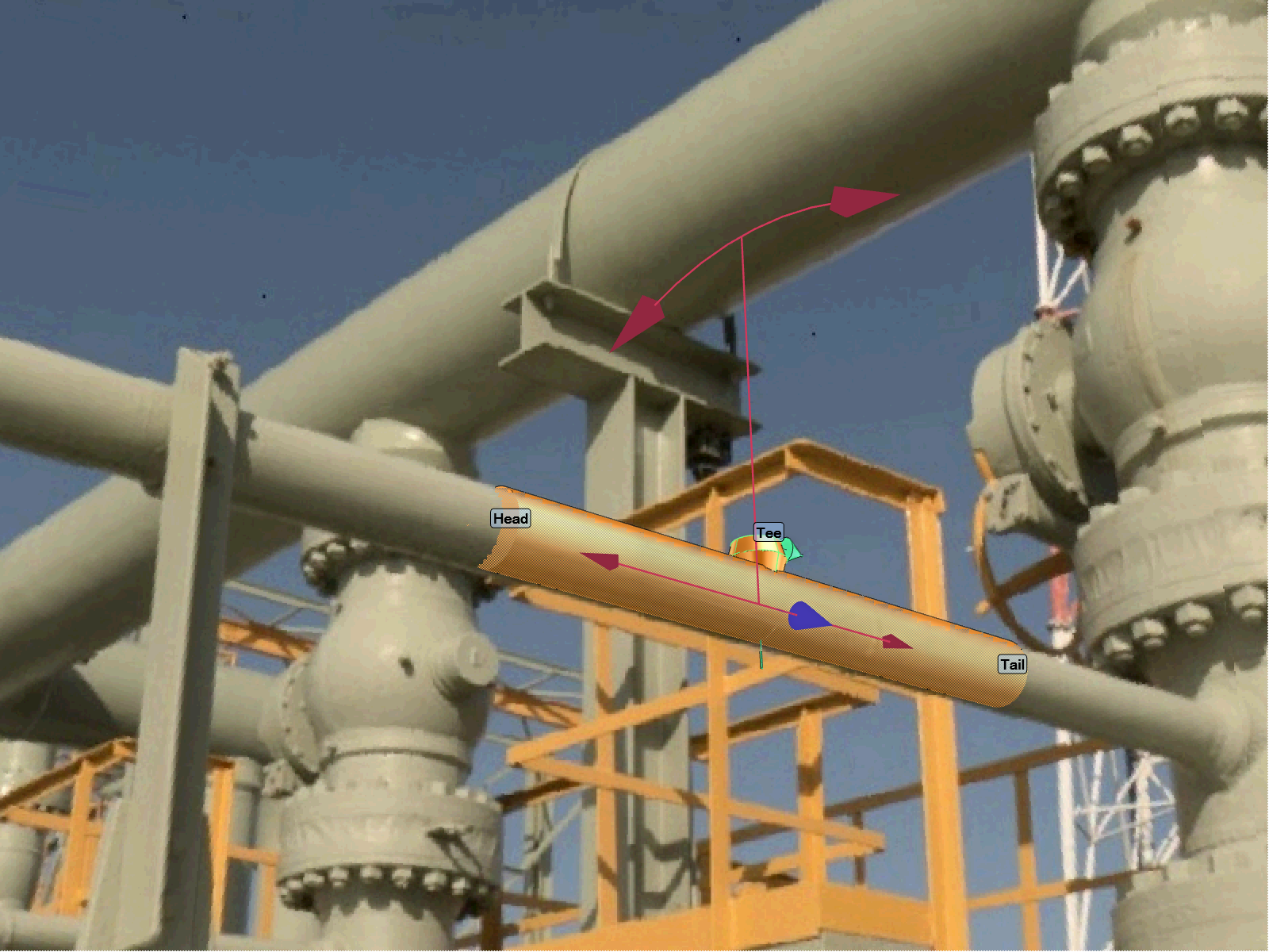

Using Quick Pipe Routing within the Piping application the new branch can be completed. Refer to Quick Pipe Routing for further information.