Common Functionality
User Guide
Laser : Tools
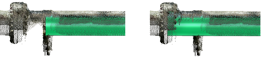
A temporary pipe aid can be introduced into the 3D view. On the Laser tab, in the Tools group, click Fit Aid to Pipe, a point should be picked on the surface of the pipe data. The process will determine the best fit cylinder diameter and also its centre line direction.
On the Laser tab, in the Tools group, click Fit Aid to Pipe to allow the AID graphic representation of the pipe to be extended or trimmed back. This is achieved by a two step process of selecting the AID graphics and then selecting a point of laser data, the result is the AID is extended in the direction to coincide with the point picked.
The user may have created a number of AID graphics representing pipes, the user can manage this data and delete them if necessary. On the Laser tab, in the Tools group, click Delete, select the following from the drop-down list:
|
•
|
Delete Aid Pipe - Select within the 3D view individual AID pipes to delete.
|
|
•
|
Delete All Aid Pipes - Deletes all AID pipes within the display
|
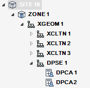
As AID graphics are not permanent, the user can choose to convert the AID pipe to a pair of design point Cartesian elements (DPCA) representing each end of the pipe, these will be stored as a member of the selected XGEOM element as a part of a design point set (DPSE). The design points generated will have the bore attribute set to the diameter of the AID pipe and the point will be orientated so the Z direction is along the centre-line of the pipe. On the Laser tab, in the Tools group, click Aid to D-Points.
By default the design points created will be orientated so the Z axis will point towards each other, the user has the option to flip selected design point orientation by 180 degrees for use in down stream operations. On the Laser tab, in the Tools group, click Invert D-Points and select the D-Point to invert in the 3D view.
If the user has defined a design point from the laser data it is possible to set the current branch element head position (HPOS) to the Cartesian co-ordinate and head direction (HDIR) to the Z direction of selected design point. On the Laser tab, in the Tools group, click Snap Head to D-Point.
If the user has created design points from the AID graphics for a pipe, the user needs to be able to manage this data. On the Laser tab, in the Tools group, click D-Points to display the D-Point Information window.
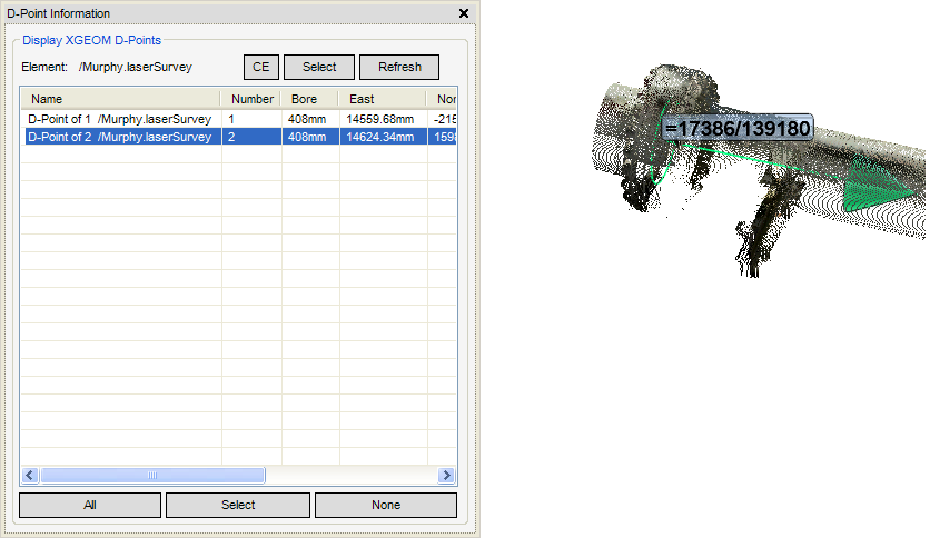
The D-Point Information window displays the list of design points associated with a selected XGEOM element and the design points will be displayed as AID graphic showing the orientation and bore of the design point. The selected design points have additional design point labelled with the name or database reference attribute in the 3D view. If the user right clicks on a design point, the following right click menu options are displayed:
 |
|