Common Functionality
User Guide
Design Aids : Move : Distance
The user can move the Origin of an element in a specified direction and distance or move it in relation to a reference point (P-Point) or another element.
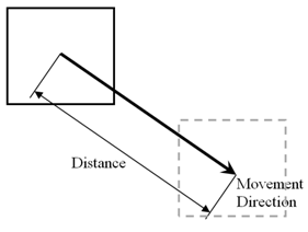
The distance is measured in the same direction as the direction of movement unless a Reference Plane option is selected.
The user must first select the element to be moved in the Model Explorer or in the 3D graphical view. On the Home tab, in the Common group, click Position Relatively By, select Move from the drop-down list to display the Move window with the Distance tab displayed.
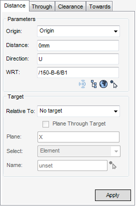
The Parameters pane displays the following options:
From the Origin drop-down menu select Origin or the P-Point that is used as the reference point for the move.
Enter the Direction of movement and an element in the WRT field that defines the frame of reference for the direction. The user can select WRT from the following options:
|
|
|
|
|
|
|
|
|
|
|
The Target pane displays the following options:
The Relative To option specifies how the element is positioned in relation to the target element or position:
|
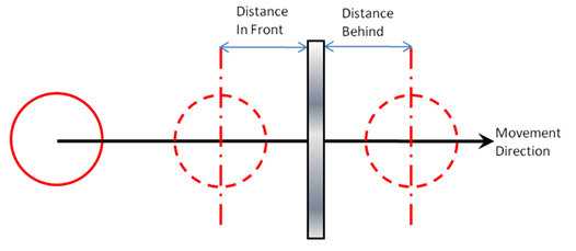
The origin of the CE is moved In front of the surface of the reference element. There must be a plan component in the direction.
|
|
The origin of the CE is moved Behind the surface of the reference element. There must be a plan component in the direction.
|
|
|
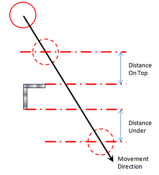
The origin of the CE is moved Ontop the surface of the reference element. There must be an elevation component in the direction.
|
|
The origin of the CE is moved Under the surface of the reference element. There must be an elevation component in the direction.
|
|
|
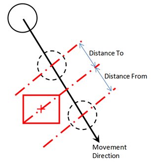
The origin of the CE is moved until it is the specified distance From the origin of the reference element.
|
|
The origin of the CE is moved until it is the specified distance Towards the origin of the reference element.
|
Select the Plane Through Target check box to allow the current element to be moved so that its origin moves a given distance in a given direction. Where the distance is measured from the intersection of the direction of movement and the reference Plane (the Plane text field becomes active when Plane Through Target check box is selected). The reference Plane is specified relative to a reference item. The Plane must not be parallel to the direction of the movement.
The type of target item is specified by the Select drop-down list. The target can be a geometry element or a position. The following options are available:
|
Click Pick Target Element icon and pick a target element on the 3D view, to populate the Name field.
|
|
|
Click Pick Target Position icon and pick a target position on the 3D view for graphical highlight of the selected position.
|
|