DRAW
User Guide
Create and Modify Views : Create Views : Create Section View
The visual style of the of the VSI is configured by the administrator. The VSI definition in use is determined by the user defaults (refer to Modify User Defaults for further information) or system defaults (refer to Set System Defaults for further information), if unset, no VSI is created.
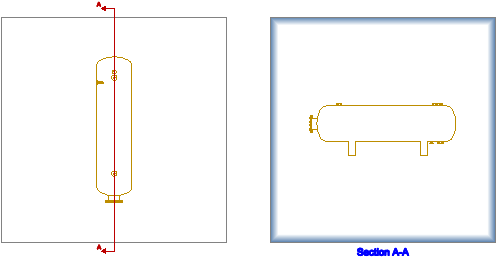
You are prompted to Select view
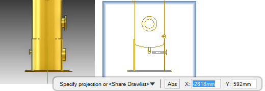
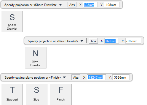
You are then prompted to Specify projection or <Share Drawlist>
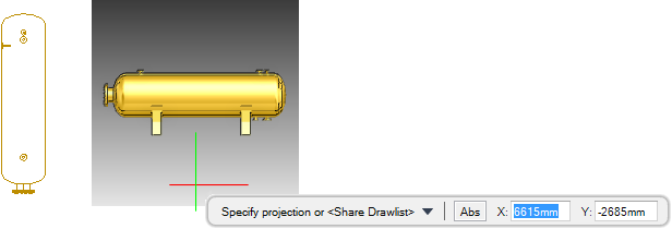
Input values in the dimension fields and press Enter or move the cursor the required distance away from the original view, click to confirm the location of the view. The projection view is created.
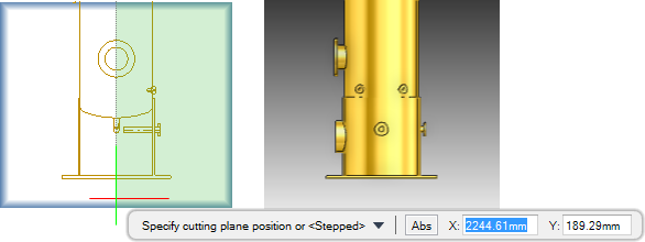
You are then prompted to Specify cutting plane position or <Stepped>
Input values in the dimension fields and press Enter or click to identify the required cutting plane.
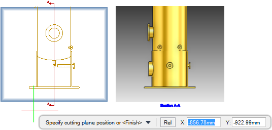
You are then prompted to Specify cutting plane position or <Finish>
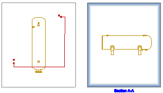
Input F at the prompt and press Enter to end the command. The section view is created. A view section indicator is also created to indicate the location of the section plane on the source view.
Throughout the view creation process you can press ESC to cancel the command. Additional functionality is also available.
|
Press the down arrow key and select Share Drawlist to reference the drawlist from the source view drawlist.
|
|
|
Press the down arrow key and select New Drawlist to create a new drawlist as a copy of the source view drawlist.
|
|
|
Press the down arrow key and select Stepped to create a stepped section view. Refer to Create Stepped Section View for further information.
|
|
|
Press the down arrow key and select Side to define which side of the cutting plane displays in the section view. A hatched area indicates the side of the cutting plane that an area of the view is removed from.
|
|
|
Press the down arrow key and select Finish to end the command.
|
|
You are prompted to Select view
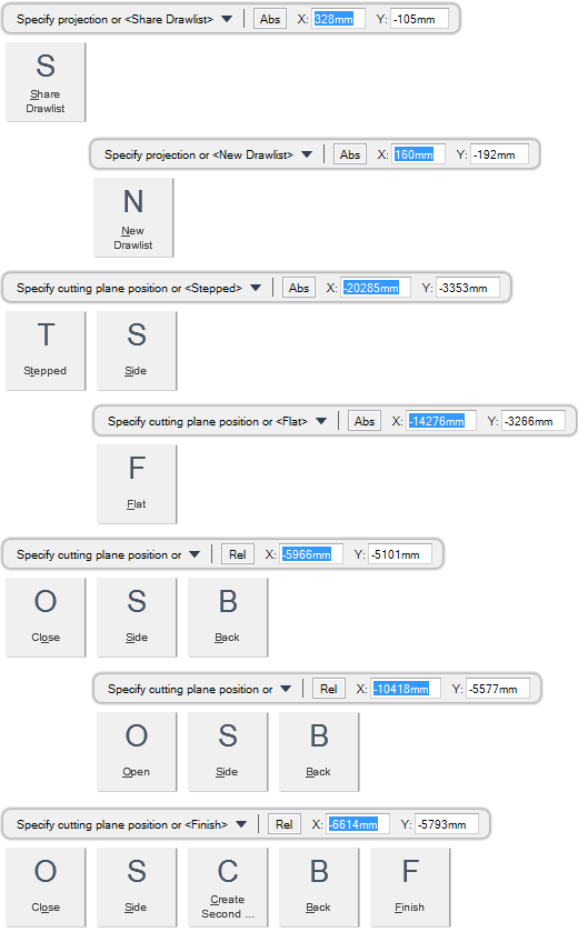
You are then prompted to Specify projection or <Share Drawlist>
You are then prompted to Specify cutting plane position or <Stepped>
You are then prompted to Specify cutting plane position <or Flat>
Input values in the dimension fields and press Enter or click to identify the cutting plane position.
You are then prompted to Specify cutting plane position or
You are then prompted to Specify cutting plane position or <Finish>
Input F at the prompt and press Enter to end the command. The stepped section view is created. A view section indicator is also created to indicate the location of the section plane on the source view.
Throughout the view creation process you can press ESC to cancel the command. Additional functionality is also available.
|
Press the down arrow key and select Share Drawlist to reference the drawlist from the source view drawlist.
|
|
|
Press the down arrow key and select New Drawlist to create a new drawlist as a copy of the source view drawlist.
|
|
|
Press the down arrow key and select Stepped to create a stepped section view.
|
|
|
Press the down arrow key and select Side to define which side of the cutting plane displays in the section view. A hatched area indicates the side of the cutting plane that an area of the view is removed from.
|
|
|
Press the down arrow key and select Flat to create a flat section view. Refer to Create Flat Section View for further information.
|
|
|
Press the down arrow key and select Close to create a closed cutting plane.
|
|
|
Press the down arrow key and select Back to undo the last action.
|
|
|
Press the down arrow key and select Open to create an open ended cutting plane by moving the cursor across the view.
|
|
|
Press the down arrow key and select Create Second to create a second cutting plane.
|
|
|
Press the down arrow key and select Finish to end the command.
|
|
The rest of the procedure is as described in Create Flat Section View or Create Stepped Section View, the difference being that a shaded area displays instead of a preview image.

