Piping
Model Pipe : Slope
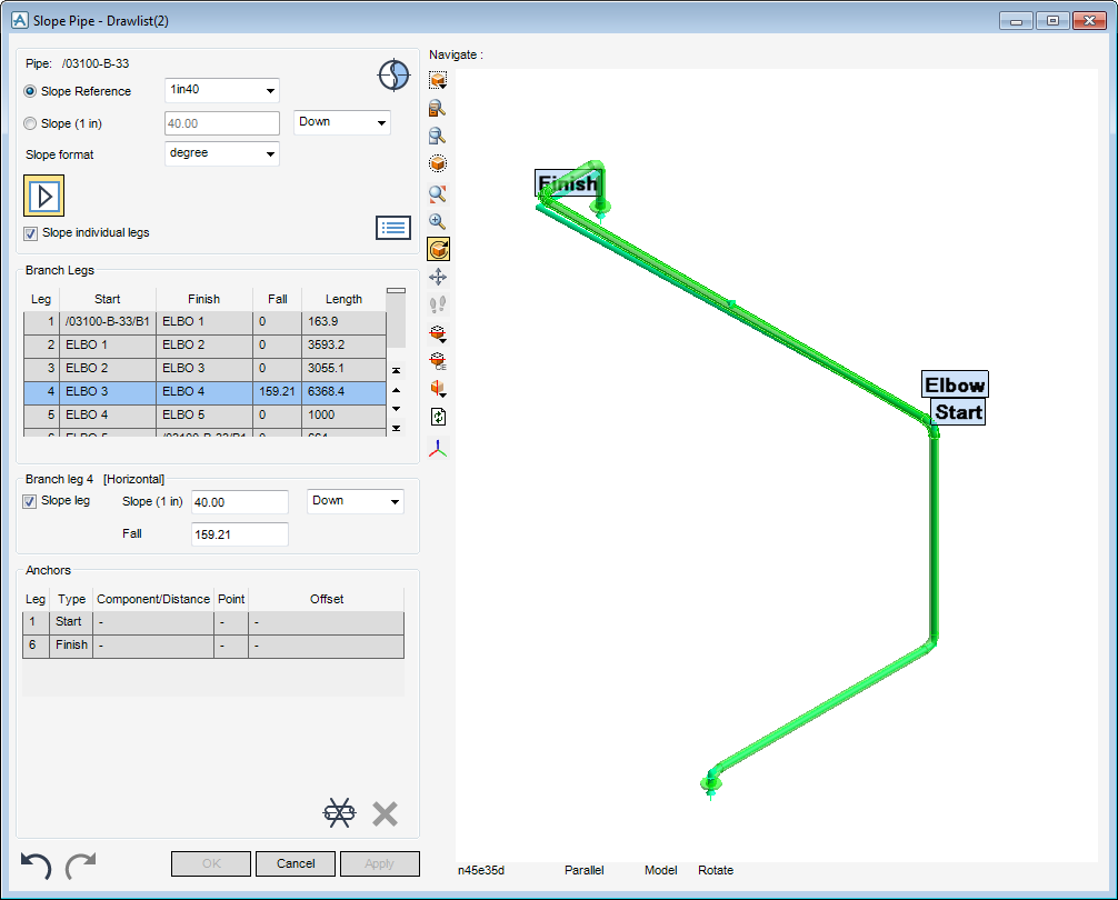
Use the dual purpose window Slope Pipe window to view the details of the CE and if required define and apply a slope to any number of branches contained within the pipe element.
|
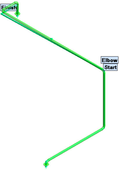
Displays a 3D pictorial representation of the CE, refer to 3D Preview Pane for further information.
|
|
|
Displays the details on the CE and the slope to be applied to it, refer to Pipe Details for further information.
|
|
|
Displays the details for the branch legs which are contained within the CE, refer to Branch Legs for further information.
|
|
|
Define the slope for a branch leg, refer to Branch leg for further information.
|
|
|
Displays the details for the anchor points, refer to Anchors for further information.
|
|
Note:
|
The CE is not actually sloped until Apply is selected.
|
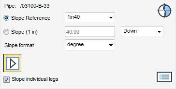
The Pipe Details pane of the Slope Pipe window displays the CE, the slope reference, the slope angle, the direction of the slope and the slope format.
Select a slope gradient from the Slope Reference drop-down list to display a preview of the slope in the 3D Preview Pane.
Alternatively, input a slope value into the Slope field and select the slope direction from the slope drop-down list.
Select a slope angle from the Slope Format drop-down list, the defined Slope Format displays in the Slope field.
Click to check the Slope individual legs check box to apply a slope to an individual branch leg. Any previously calculated slope is removed from the 3D Preview Pane display.
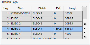
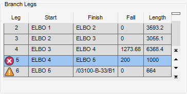
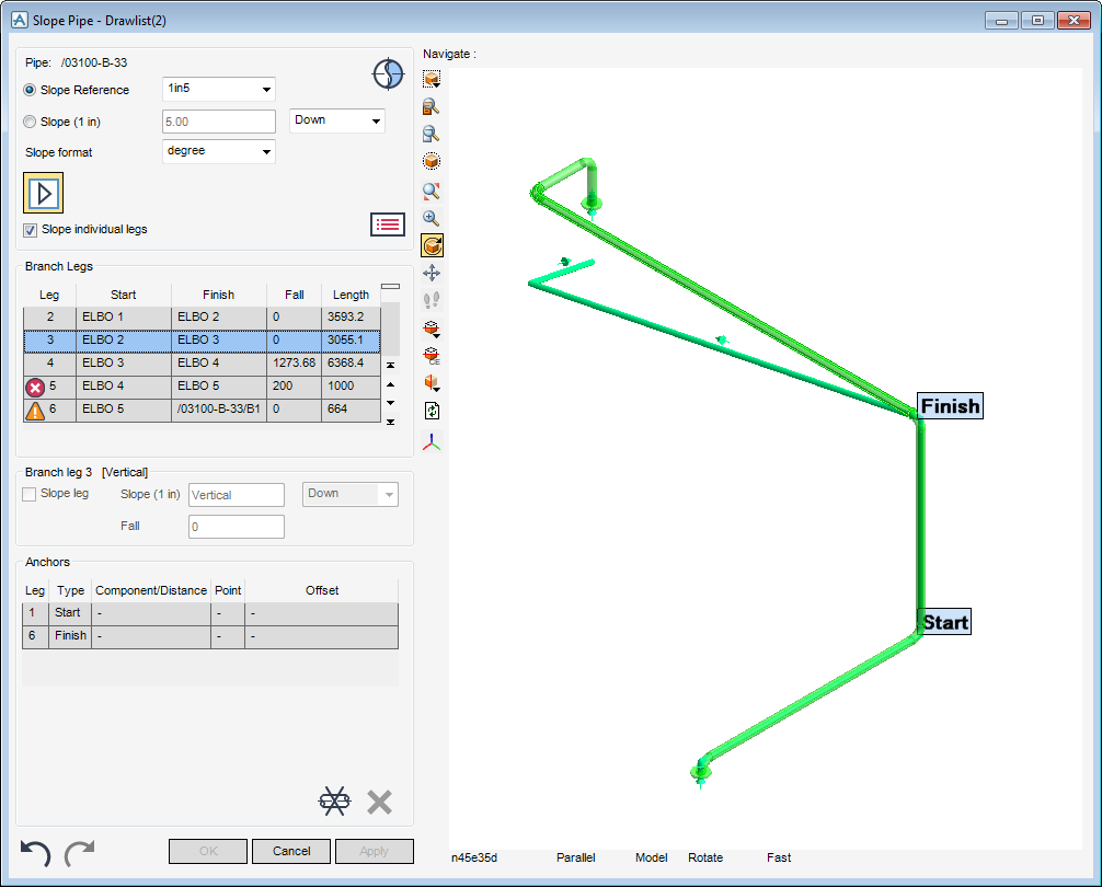
The Branch Legs pane of the Slope Pipe window displays a numbered list of the branches and the components within the current pipe. In addition to the start and finish component for the branch leg, the list includes the length of the leg and the fall of the leg when the slope is applied. Vertical branch legs are not sloped and therefore always have a drop of zero.
During the sloping process the Slope Pipe window lists the components selected for modification which produce a warning or caution. Click Error Messages have been generated by the slope calculation to view the details of the error.
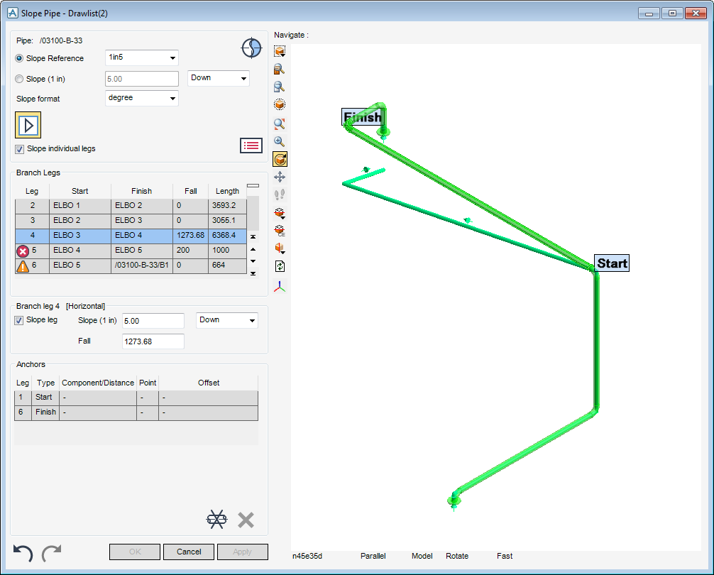
Once an entry has been selected from the list of available legs, the Branch leg pane of the Slope Pipe window is automatically populated with the functionality to anchor the selected branch leg and if available modify the slope. The pictorial representation of the CE is automatically labelled.
Select the Slope leg check box to specify that the selected branch leg to be sloped, or select to uncheck the Slope leg check box to force the selected branch leg to be horizontal.
Specify the values for the slope, type the slope directly into the Slope field, the default slope format is defined from the selected Slope format in the Pipe Details pane of the Slope Pipe window. The Fall field is automatically populated with the correct value for the slope. These fields can be populated the other way round if required.
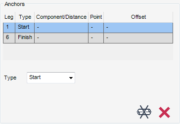
The Anchors pane of the Slope Pipe window displays a numbered list of the branch legs within the current pipe. In addition to the anchor type, the list includes the component/distance for the branch leg, the point and the offset for the anchor.
The anchor type is used to specify the position of anchors. The anchor types available for selection from the Type drop-down list are:
When the Component anchor types is selected, the Anchors pane of the Slope Pipe window is automatically updated with further fields requiring input.
|
The prompt ‘Pick position (Distance [0]) Snap :’ is displayed in the 3D Preview Pane. Click a position in the 3D Preview Pane to place an anchor.
|
The Component drop-down list identifies the component to which the anchor is to be positioned.
The Point drop-down list determines where on the picked component the anchor is to be positioned, select Top, Centre or Bottom.
To offset each anchor from the previous one by a specified distance relative to a picked position on the picked element., type the distance in the Offset field, select where to position the anchor relative to a position on the picked element.
When the Position anchor type is selected, the Anchors pane of the Slope Pipe window is automatically updated with further fields requiring user input.
|
The prompt ‘Pick position (Distance [0]) Snap : in’ is displayed in the 3D Preview Pane. Click a position in the 3D Preview Pane to place an anchor.
|
The horizontal distance from the start of the leg to the fixed position can be entered in the Distance field.
The Point drop-down list determines where on picked component the anchor is to be positioned, select Top, Centre or Bottom.
To offset each anchor from the previous one by a specified distance relative to a picked position on the picked element. Type the distance in the Offset field, then select where to position the anchor relative to a position on the picked element.
Any inputs into the Slope Pipe window can be reversed:

