Piping
Model Pipe
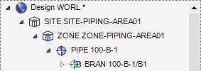
Before modelling a pipe, the correct database elements should already be present in the Model Explorer, for example, a World, Site and Zone should exist. If this is not the case, refer to Database Hierarchy for more information.
|
•
|
|
•
|
|
•
|
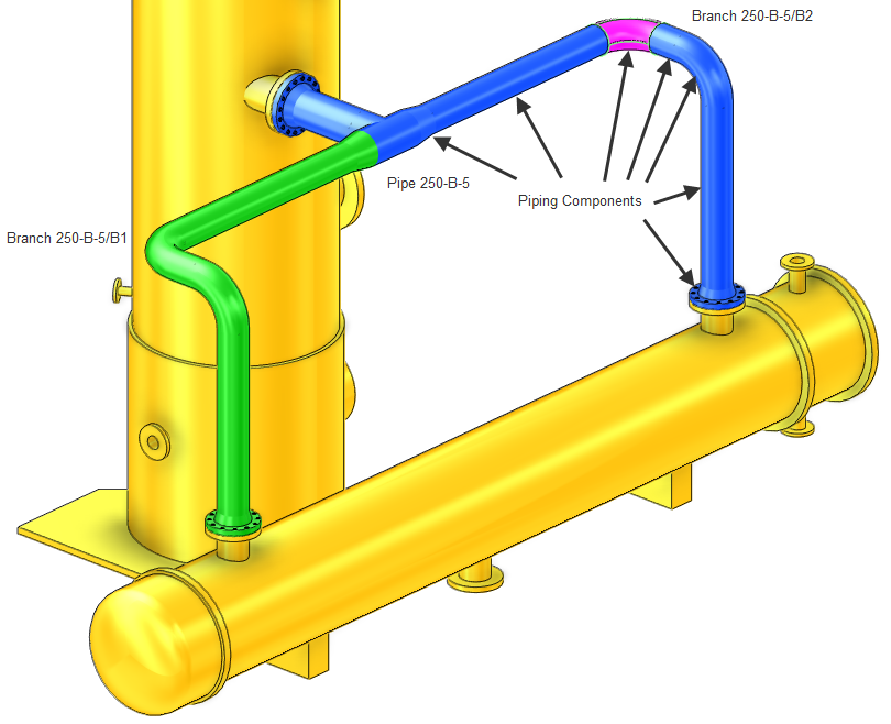
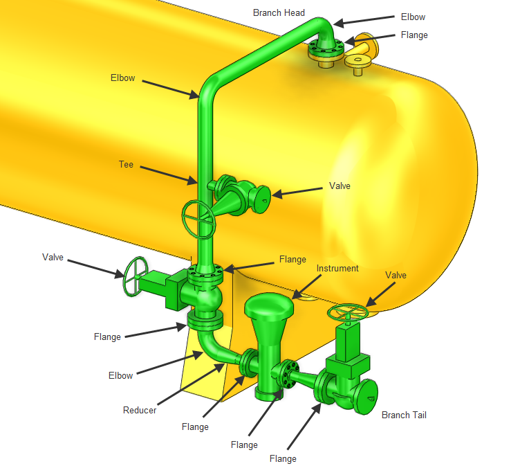
Below the zone level in the PIPING discipline, the specific elements are:
Piping elements cannot be created or modified, if the correct database hierarchy has not been configured beforehand or if the correct current element has not been selected in the Model Explorer. For example certain piping elements must reside below other elements in the database hierarchy (an overview of the database hierarchy is described in Database Hierarchy).
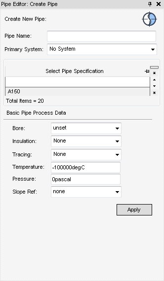
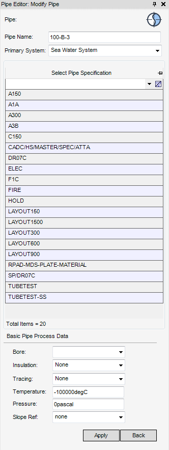
By default the Primary System is No System, to change the type of primary system select a system from the Primary System drop-down list.
The Bore specifies the nominal bore and does not affect the pipe route (the default is unset).
Select an Insulation specification, if no insulation is required (the default is None), select None.
|
Note:
|
In Temperature, enter the temperature to which the pipe can reach (the default is ‑10000degC, this means that the temperature is ignored).
In Pressure, enter the pressure to which the pipe must withstand (the default is 0pascal).
The Slope Ref specifies the slope reference attribute, which is governed by the catalogue (the default is none). To change the slope reference attribute, select a slope reference from the Slope Ref: drop-down list.
Click Apply, to create a new pipe and branch element in the Design database and display the Pipe Editor: Modify Pipe window, to define the branch, refer to Branch Element for further information.
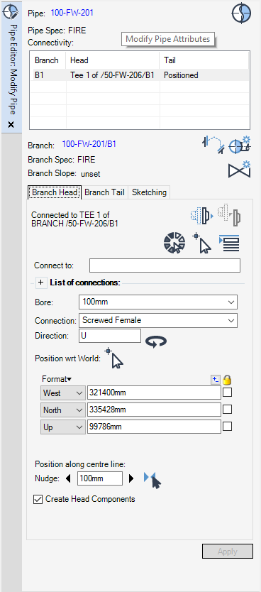
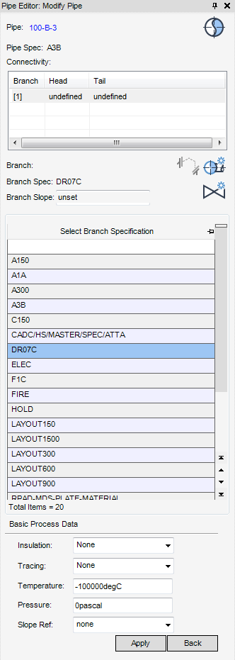
The Pipe Editor: Modify Pipe window displays by default when a new pipe element is created. It is a dual purpose window which allows the definition of branch attributes and/or connect the branch head and branch tail or modify an existing branch.
By default, the Pipe Editor: Modify Pipe window is populated with the attributes of the CE, if required, select another pipe as the CE.
Use the Pipe Editor: Pipe window to select an alternative Pipe Specification by clicking Modify Pipe Attributes to display the Pipe Editor: Modify Pipe specification window.
The Pipe Editor: Modify Pipe specification window has the same functionality as the Pipe Editor: Create Pipe window, refer to New Pipe Element for further information.
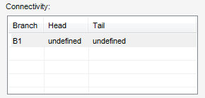
The Connectivity part of the Pipe Editor: Modify Pipe window displays the connectivity status of each branch within the pipe assembly.
If required, select an alternative Branch Specification by clicking Modify Branch Attributes to display the Pipe Editor: Modify Pipe branch specification window.
The Pipe Editor: Modify Pipe branch specification window has the same functionality as the Pipe Editor: Create Pipe window, refer to New Pipe Element for further information.
|
Creates a new branch for the pipe assembly. Refer to Create Other Branches for further information.
|
||
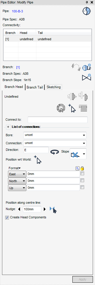
The Branch Head and Branch Tail tabs on the Pipe Editor: Modify Pipe window, are used to define the connection and position of the branch head or branch tail. As the functionality for the definition of the branch head or branch tail is identical, for the purposes of this user guide, only the branch head definition is described. By default the branch head tab is selected when the Pipe Editor: Modify Pipe window displays.
For example, to define the head of the branch, make sure the correct branch is highlighted in the design database and the correct branch name displays in the Connectivity part of the of the Pipe Editor: Modify Pipe window.
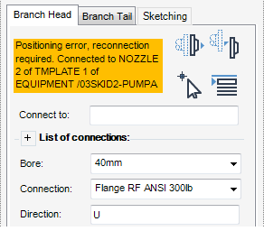
The Branch head tab of the Pipe Editor: Modify Pipe window is used to connect the branch head and define basic branch head details, the connection status of the selected branch displays by default:
|
Selects the head/tail position, orientation of laser data, refer to Laser Data for further information.
|
||
|
Connects the branch head to a selected element, refer to Connect Branch Head to Element for further information.
|
||
|
Connects the branch head to the first branch member, refer to Connect Branch Head to First Branch Member for further information.
|
As an alternative to connecting the branch head on the 3D graphical view, input the name of the equipment element in the Connect to field.
In the Bore drop-down list, select the nominal bore of the pipe from the list of available sizes in the catalogue.
In the Connection drop-down list, select the type of head connection from the list of available connections in the catalogue.
The Direction specifies which direction the flow takes from the Branch Head. (The head direction is the direction of flow and the tail direction is the opposite direction of the flow).
|
Reverses the head/tail direction (used with Laser Modelling). Refer to Laser Data for further information.
|
|
Use the Position wrt World: part of the Pipe Editor: Modify Pipe window to position the branch head explicitly.
|
The prompt Modify Pipe - Select Head Position (Distance[0]) Snap: is displayed.
|
If required use the positioning aids available for selection from the Positioning Control window, to select the head position on the. 3D graphical view.
If required, nudge the head direction, from the Position along centre part of the Pipe Editor: Modify Pipe window. The nudge distance is controlled by the nudge increment which is set to 100mm by default.
Pick the head position along a selected centre line, from the Position along centre part of the Pipe Editor: Modify Pipe window, click
|
The prompt Modify Pipe - Select Head Position (Distance[0]) Snap: is displayed.
|
Select the Create Head Components checkbox to create gasket/flanges at the head.
Click Apply to create the head/tail.
Click Set working pipe, to identify the element as the CE, the attributes of the element are automatically populated in the Pipe Editor: Modify Pipe window.
The Branch Head tab of Pipe Editor: Modify Pipe window indicates that the selected branch head is connected.
From the Branch Head tab of the Pipe Editor: Modify Pipe window, click Disconnect head to disconnect the branch head from the element it is connected to.
Click Set working pipe, to identify the element as the CE. The attributes of the element are automatically populated in the Pipe Editor: Modify Pipe window.
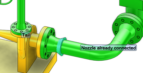
The Branch Head tab of Pipe Editor: Modify Pipe window indicates that the selected branch head is connected but requires reconnection.
Click Reconnect to reconnect the branch head to the equipment element.
Click Set working pipe, to identify the element as the CE, the attributes of the element are automatically populated in the Pipe Editor: Modify Pipe window.
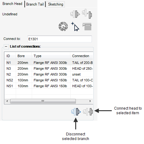
The Branch Head tab of Pipe Editor: Modify Pipe window indicates that the selected branch head is undefined.
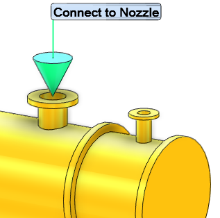
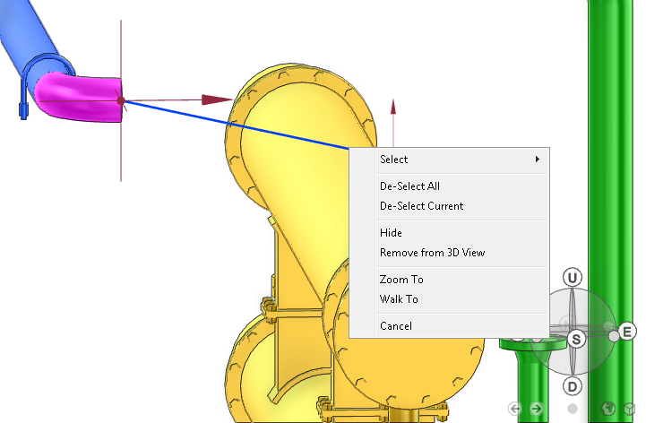
From the Branch Head tab of the Pipe Editor: Modify Pipe window, click Pick item to connect head to, then Identify element to connect to:, select the element to connect to in the 3D graphical view.
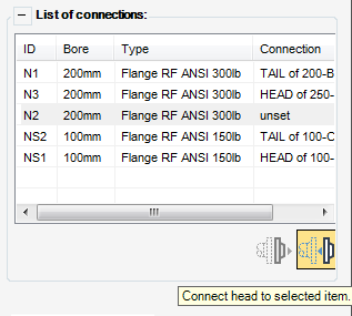
The List of connections: is populated and displays the connection status of each connection component.
Select a component from the List of Connections:.
The Connect functionality is only available for selection when the connection from the List of connections part of the Pipe Editor: Modify Pipe window is Unset.
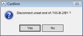
Connect the branch to the selected element in the List of Connections. Alternatively a connected branch can be disconnected from an element.
|
Click Yes to disconnect the selected connection.
|
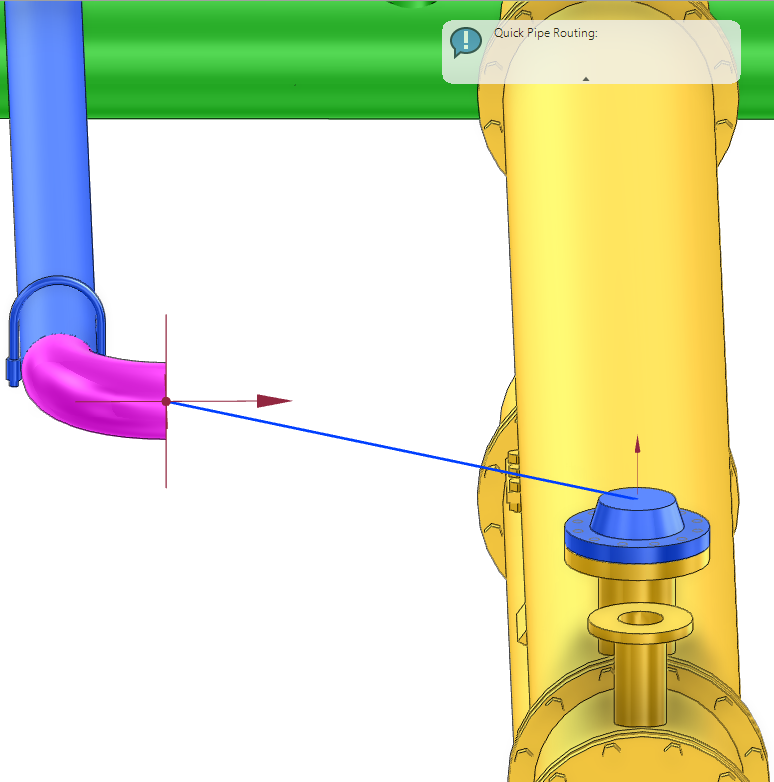
Once the branch head and branch tail has been defined or selected, the branch now consists of a single piece of pipe running between the branch head and branch tail. The branch displays a red dotted line, which means the branch route is geometrically incorrect a pipe run can now be created, refer to Quick Pipe Routing for further information.
|
Note:
|
The slope functionality is only available in the piping discipline, refer to Slope for further information.
|
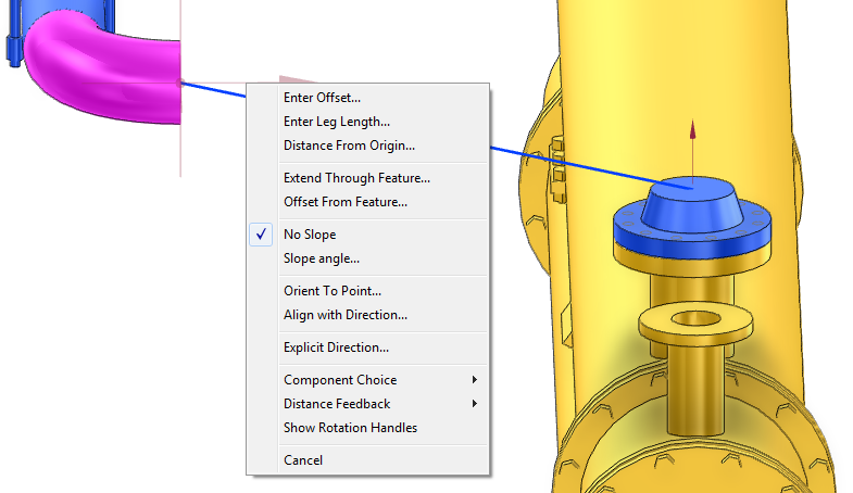
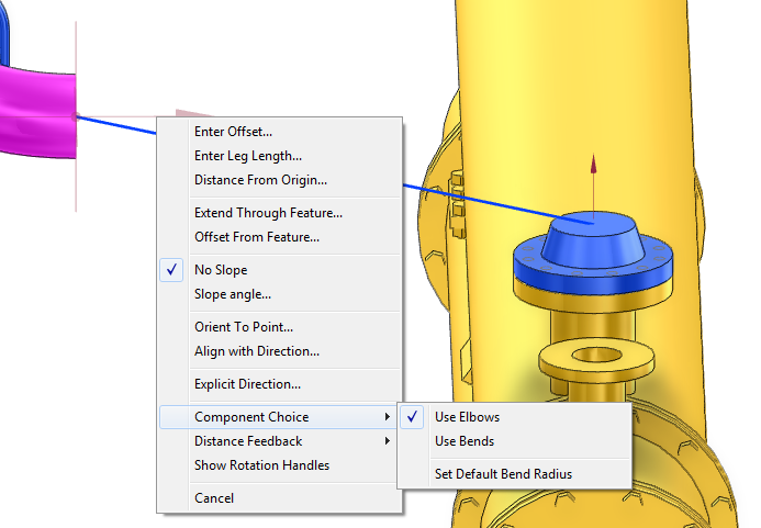
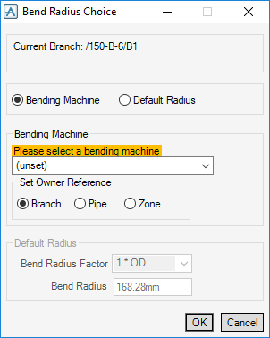
From the quick pipe routing right click menu, select Component Choice > Set Default Bend Radius, the Bend Radius Choice window is displayed. The Current Branch is displayed and Bending Machine is selected as default.
The Bending Machine part of the Bend Radius Choice window indicates that the bending machine must be selected.
Once a bending machine has been selected from the list of available machines, the bendmacreference on either the branch, pipe or zone is assigned depending on the selected Set Owner Reference.
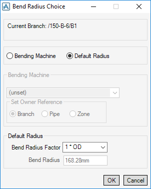
Alternatively, the default radius can be defined using the Default Radius functionality, from the Bend Radius Choice window select Default Radius.
Bend Radius Factor - Use the bend radius factor to specify a factor which takes the current tube outside diameter and multiplies it by the factor available for selection from the Bend Radius Factor drop-down list. The bend radius factor is l then be used on all subsequent bends giving the appropriate radius according to their outside diameter.
Bend Radius - Explicitly enter a radius in the Bend Radius field, the bend radius is then be used on all subsequent bends giving the appropriate radius according to their outside diameter.
To automatically route multiple or single pipes orthogonally and with the minimum number of bends or elbows and where possible clash-free, refer to Pipe Router for further information.
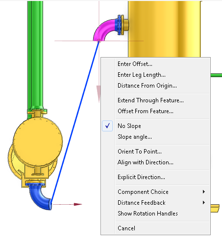
By default, No Slope is selected (no slope will be applied to the pipe leg). To set the sloping angle, select Slope Angle, the Set Slope Angle window is displayed.
Enter the sloping angle, click OK to apply the sloping angle, quick pipe router will route the pipe with the sloping angle or click Cancel to discard any inputs and close the window.
|
Note:
|
If the default slope is set on a pipe or branch then extra functionality is available for selection, Default Slope Up and Default Slope Down. When selected, quick pipe router would route the pipe in accordance with the selected default slope.
|
Click Set working pipe, to identify the element as the CE, the attributes of the element are automatically populated in the Pipe Editor: Modify Pipe window.
Click Connect head to first branch member to connect the branch head to the first member of the branch.
To create a new branch under the pipe element identified as the CE, from the Pipe Editor: Modify Pipe window, click Create a new branch.
A new branch is created in the Model Explorer and in the Connectivity part of the Pipe Editor: Modify Pipe window. Populate the Pipe Editor: Modify Pipe window with details and connections as required. Refer to Define Branch Head and Branch Tail for further information.
Pipe Sketching
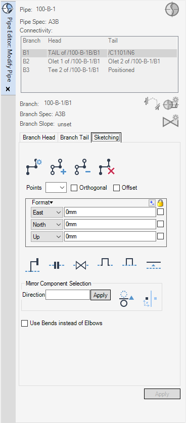
Use the Pipe Sketching functionality to access design aids and tools to create a branch, insert components, copy and mirror piping components.
Select an aid point from the Points drop down list, to view the frame, offset and world position of an aid point.
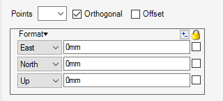
Use the Orthogonal functionality to view the line between the aid points in the 3D graphical view as orthogonal.
Use the Offset functionality to offset an aid point in the 3D graphical view.
Use the Mirror Component Selection functionality to mirror an existing branch element.
|
Use to enter a direction for the mirror into the Direction field. Once an element has been picked in the 3D graphical view, a mirror plane is displayed in the 3D graphical view.
|
||
|
Use the Pick Mirror Direction functionality to pick a direction in the 3D graphical view. After a element has been picked in the 3D graphical view, a mirror plane is displayed in the 3D graphical view.
|
||
|
Use to pick a mirror position in the 3D graphical view. Once selected the Positioning Control toolbar is displayed. Use its functionality to position the mirror plane.
|
||
Referring to the Database Hierarchy, a pipework component must reside below an existing pipe branch element. Refer to Branch Element for a more detailed explanation of creating a pipework branch.
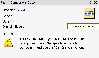
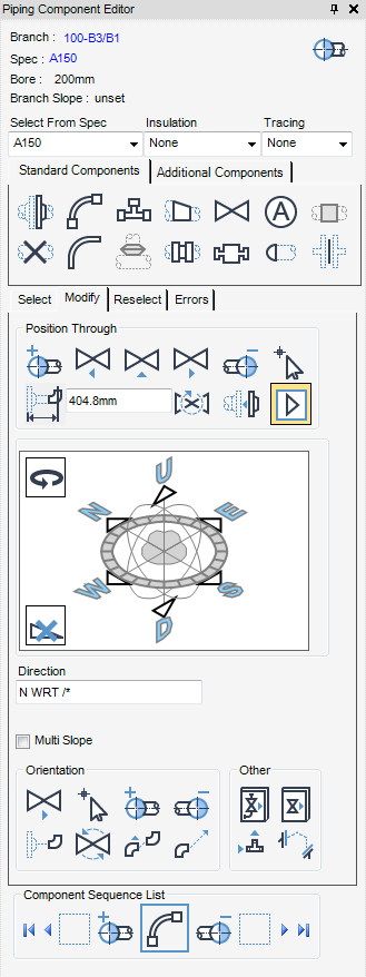
Select the correct branch element from the Model Explorer and click Set working pipe to display the Piping Component Editor window.
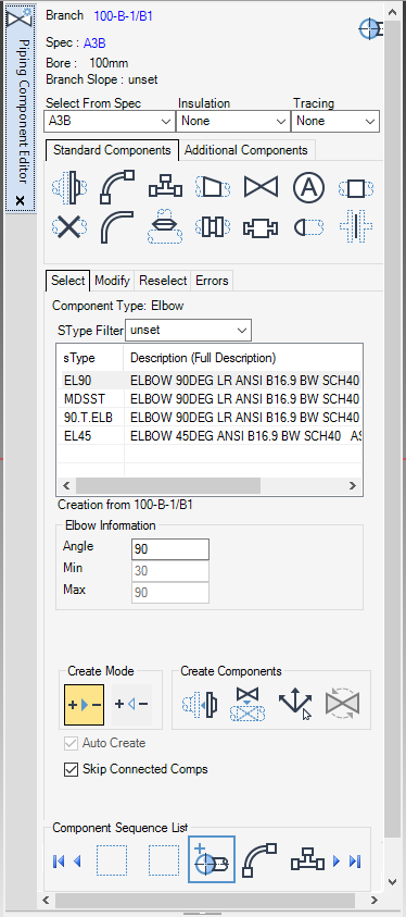
The Spec:, Bore: and Branch Slope: of the currently selected pipe displays at the top of the window.
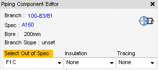
Select a specification from the Select From Spec drop-down list. If a specification is selected that does not match the pipe specification, the Piping Component Editor window displays a Select Out of Spec message.
Select an insulation specification from the Insulation drop-down list. If no insulation is required, select None. (If a new specification is required, refer to the system administrator).
Select a tracing from the Tracing drop-down list. If no tracing is required, select None. (If a new specification is required, refer to the system administrator).
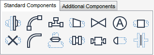
The Standard Components tab (displayed as default) provides quick access to the more commonly used components.
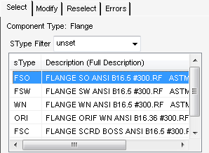
The Select tab displays all of the components available for selection from the catalogue under the currently selected component and piping specification.
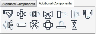
The Additional Components tab provides quick access to further components
The Select tab displays all of the additional components available for selection from the catalogue under the currently selected piping specification.
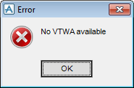
If the selected component is not available from the catalogue an Error window displays.
Click OK to select another component.
The component information part of the Piping Component Editor window displays information specific (if relevant) to the selected standard or additional component.
Click Flange from the Standard Components tab to display the Reducing Flange Information in the Piping Component Editor window.
The Leave Bore drop-down list is not used for a flange.
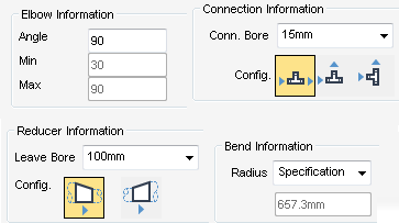
Click Elbow from the Standard Components tab to display the Elbow Information in the Piping Component Editor window.
Click Tee from the Standard Components tab to display the Connection Information in the Piping Component Editor window.
Select a value from the Conn Bore drop-down list.
Click Reducer from the Standard Components tab to display the Reducer Information in the Piping Component Editor window.
Select a value from the Leave Bore drop-down list.
Click Bend from the Standard Components tab to display the Bend Information in the Piping Component Editor window.
Select a value from the Radius drop-down list.
Click Olet from the Standard Components tab to display the Connection Information in the Piping Component Editor window.
Select a value from the Conn Bore drop-down list.
Click Coupling from the Standard Components tab to display the Reducing Coupling Information in the Piping Component Editor window.
Select a value from the Leave Bore drop-down list.
Click Assembly from the Additional Components tab to display the Assemblies part of the Piping Component Editor window.
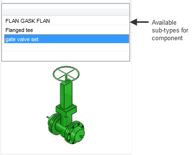
Choose from a list of available assemblies in the Available sub-types for component drop-down list. The assemblies available for selection are those already created in the catalogue, if the required assembly is not included, refer to the system administrator.
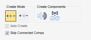
Use the Create Mode part of the Piping Component Editor window to set the direction of flow, the software creates the component in the Head to Tail direction by default.
If the Auto. Create check box is selected, the software automatically determines if there is a requirement for an associated component (on a valve, the associated component would be a flange and gasket) and if so, what is the appropriate.
If the Out of Spec check box is selected, an alternative specification component can be used.
If the Skip Connected Comps check box is selected, the pipework application automatically determines which components are connected, then positions the creation point approximately.
Use the Create Components part of the Piping Component Editor window to connect or place the component.
|
Identify the branch leg for the component on the 3D graphical view, for example identify branch leg for Elbow: displays when an elbow is the selected component.
|
Use the Create Assemblies part of the Piping Component Editor window to connect or place the assembly.
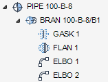
Use the Component Sequence List part of the Piping component Editor, to scroll through and select individual components within the currently selected branch.
The CE is highlighted in the centre of the Component Sequence List, if required select another component in the sequence list.
|
Note:
|
The sequence direction is determined by the routing direction, refer to Position Through for further information.
|
To continue routing pipework, select the component from the chosen specification, then position and set orientation using the Editor, (refer to Editor for further information).
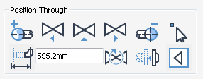
Use the Position Through part of the Piping Component Editor window to adjust the position of a component.
|
Displays the Positioning Control window. For more information, refer to Positioning Control for further information.
|
||
|
Displays the actual clearance, to change the clearance input a new value into the text field then press Enter. To modify the distance, click the Distance - Click to use Clearance toggle, refer to Distance - Click to use Distance for further information.
|
||
The 3D Compass part of the Piping Component Editor window can be used in two ways depending upon the type of component selected. By default, the Direction Tool is displayed as default.
Direction Tool: the direction of elbows and bends can be changed.
Rotation Tool: tees and other non-symmetrical components such as valves or reducers can be rotated.
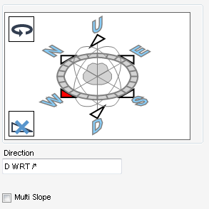
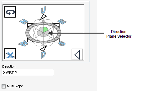
Use the Direct Component view displays a compass which to set the orthogonal direction of a component using the direction arrows and the direction plane selector of the compass.
|
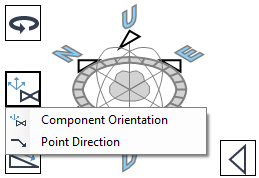
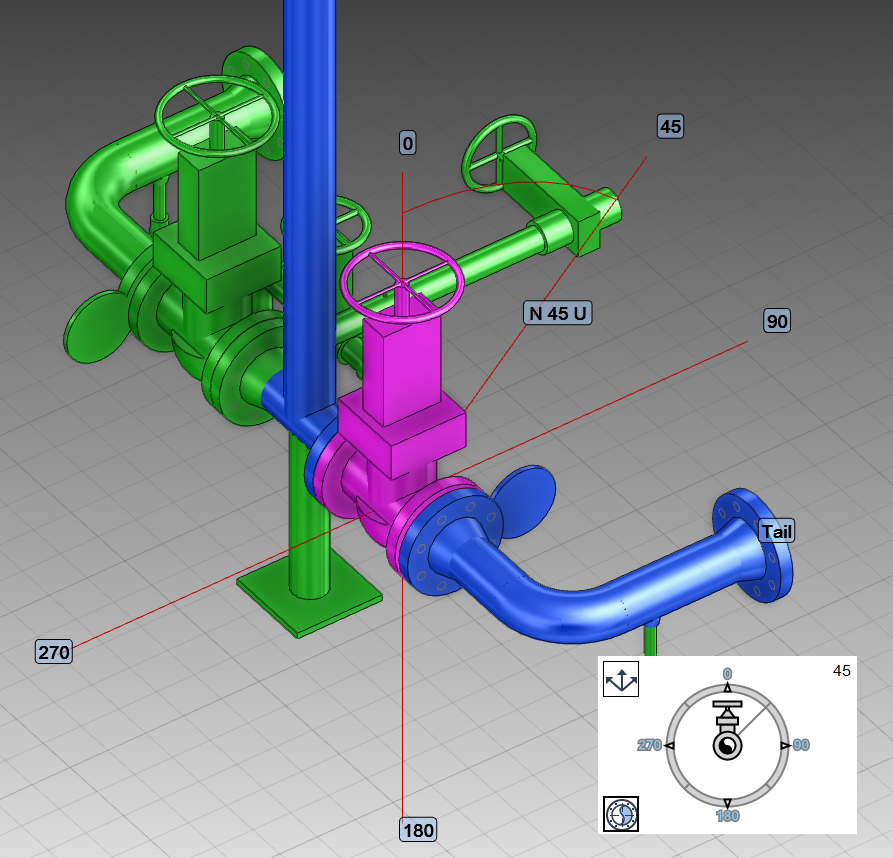
Use the right click menu from the Direction Display part of the Create/Modify Pipe Component window to define the ISO view and coordinate system.
|
||
|
Use to rotate the component, refer to Rotation Tool for further information.
|
||
|
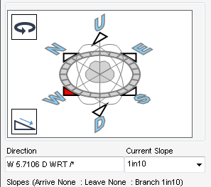
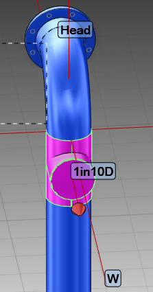
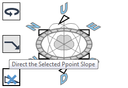
Use to set the current slope to up or down, refer to Slope for further information.
|
||
|
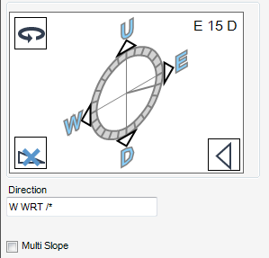
Use to input a desired direction in the Direction field, for example, input E in the Direction field to set the orthogonal direction of the component to face the E axes.
|
||
To direct the component using a direction plane, click the Direction Plane Selector of the direction tool to set the direction plane. For example, click the top right section of the Direction Plane Selector to change the direction plane. The direction plane displayed depends upon the original orientation of the component.
If required, add a slope to the orthogonal direction of the component, from the 3D compass view, click Set the current slope to Up or Down.
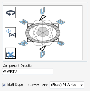
To select an individual ppoint on a component for both orientation and direction change, select the Multi Slope check box to display the Current Point drop down list.
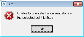
If the ppoints are fixed, an Error window is displayed.
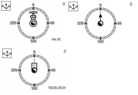
Use the Rotation Tool to change the rotation orientation of a component using the rotation dial. Click Rotate Component to display the Rotation Tool. Dependent upon the currently selected component determines how the rotation tool is displayed.
|
Use to return to the direction tool, refer to Component Direction for further information.
|
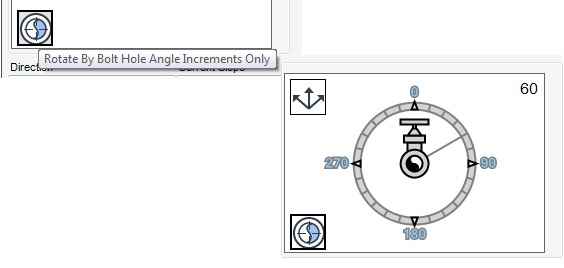
Use the Bolt Hole Alignment window to rotate a flanged component so that it aligns with the bolt hole spacing by default, which means using the number of bolt holes in the component to determine the default angle increments of rotation.
To remove the constraint and rotate the component without aligning to the bolt holes, from the Bolt Hole Alignment window, click Rotate By Bolt Hole Angle Increments Only.
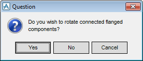
Click Rotate By Bolt Hole Angle Increments Only, then select the rotation angle which is no longer constrained by bolt hole alignment. A Question window is displayed:
Click Yes to rotate the connected flanged components to the angle.
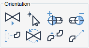
Use the Orientation part of the Piping Component Editor window to adjust the orientation of a component.
|
Displays the Drag Move window when a component is selected in the Model Explorer. Refer to Advanced Move for further information
Displays the Drag Move Branch window when a branch is selected in the Model Explorer. Refer to Advanced Move for further information.
|
||
|
Displays the Move window when a component is selected in the Model Explorer. Refer to Advanced Move for further information.
Displays the Move Branch window when a branch is selected in the Model Explorer. Refer to Advanced Move for further information.
|
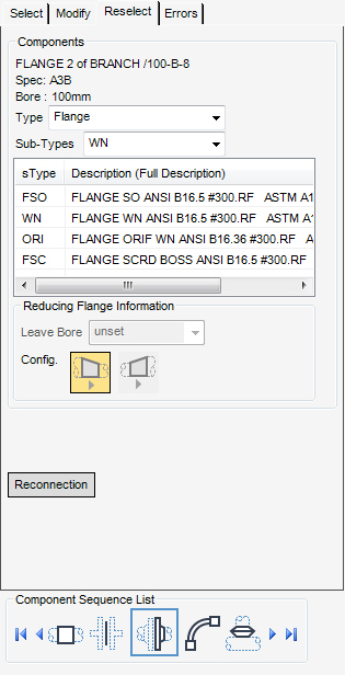
Use the Reselect tab to replace a piping component from a list of available components, select the Reselect tab to display the CE’s attributes and properties. The Reselect tab of the Piping Component Editor window displays all the components available from the catalogue under the current piping specification.
Select a component from the Type drop-down list to filter the component type to modify.
Select a component specification from the Sub-Types drop-down list to filter the component by sub-type.
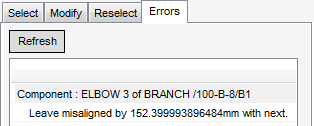
Select Reconnection to re-establish adjacent connections. If an error occurs when the components is replace, the error tab displays, populated with the error.
With the Errors tab selected, the Piping Component Editor window lists the components selected fro modification which produce an error in the selection process. An error is indicated with a description in the error list.
When the error has been rectified, click Refresh to update the error list.
If the non-standard branch connection is greyed out in the Tools group, refer to the system administrator.
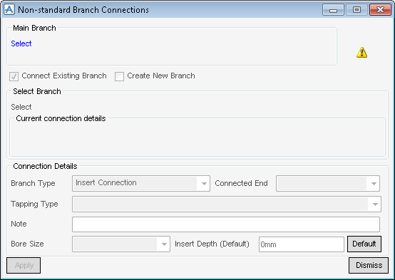
Use the Non-standard Branch Connections window to connect existing branches.
From the Main Branch pane, click Select, the prompt Identify Main Branch is displayed. Once the selection has been made, the selected branch name, bore and wall thickness are displayed in the Non-standard Branch Connections window and the Connect Existing Branch check box is automatically selected.
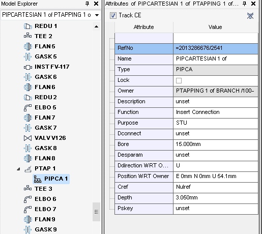
From the Select Branch pane, click Select, the prompt Identify Stub in Branch is displayed. Once the selection has been made, the branch connects to a cartesian point (PIPCA) owned by the component. The selected branch name and bore are displayed in the Non-standard Branch Connections window. As the branch is not yet connected the Current connection details part of the Non-standard Branch Connections window head and tail are not connected.
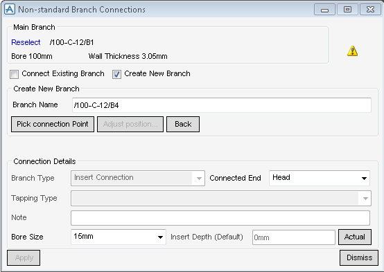
Use the Connection Details part of the Non-standard Connections window, to set the connection and tapping type, bore size and insert depth.
The Branch Type can be selected from the drop-down list:
In the Note field, add a fabrication note which will appear on the piping isometrics
The Insert Depth value varies according to the Branch Type selected and is calculated using a set of standard calculations for branches on centreline. In some cases the calculation may need to be adjusted by eye to provide a more accurate material length. To do this enter a value into the Insert Depth field. The value shown in this field can be one of three types:
|
the current value entered but not yet fixed by clicking Apply. The button to the right of the insert depth will swap the insert values between actual and default.
For example if the default is 4.75mm and the actual is 14.57mm clicking Default will change the insert depth to 4.75 and the button will have a display of Actual. Clicking it again will return the insert depth value to 14.57.
|
Click Apply to create the connection or click Dismiss to discard any inputs and close the Non-standard Connections window.
Use then Non-standard Branch Connections window to connect a new branch, click Select, the prompt Identify Main Branch is displayed. Once the selection has been made, the selected branch name, bore and wall thickness are displayed in the Non-standard Branch Connections window. Select the Connect New Branch check box.
The Create New Branch pane is automatically displayed with a name for the new branch. Click Pick connection Point, the prompt Pick a surface Position to locate initial branch position: is displayed.
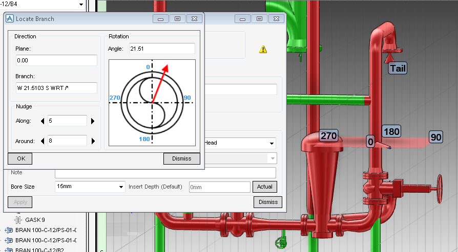
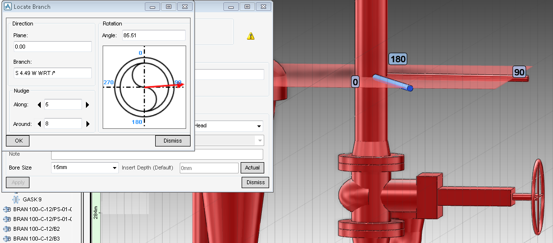
The new branch is initially positioned at the new connection point in the 3D graphical view, to adjust the position of the connection point, click Adjust position. The Locate Branch window is displayed and a positioning aid (plane) is displayed in the 3D graphical view.
The Locate Branch window is populated with the direction of the plane and branch also with the angle at which the new connection point is initially positioned.
If required, position the new connection, use the Nudge and Rotation parts of the Locate Branch window.
Click OK to position the connection at the new location or click Dismiss to discard any inputs and close the Locate Branch window.
From the Connection Details pane, set the connection and tapping type, bore size and insert depth.
Click Apply to create the connection or click Dismiss to discard any inputs and close the Non-standard Connections window.

