Piping
Spool Drawings : Configuration
All of the design objects created and/or modified using the functionality available from the Configuration group are stored in APPLDW’s.
Although the functionality available from the Fabrication Machine Manager window differs depending on which machine selected from the Machine Type drop-down list. The Options part of the Fabrication Machine Manager window is common, throughout.
Fabrication checks requests are made to a fabrication machine manager controlling the fabrication machines. Information about the welding/bending machine operation and their corresponding activity tables can be obtained from the Manager. Refer to Fabrication Machine and Automatic Flange Alignment for further information.
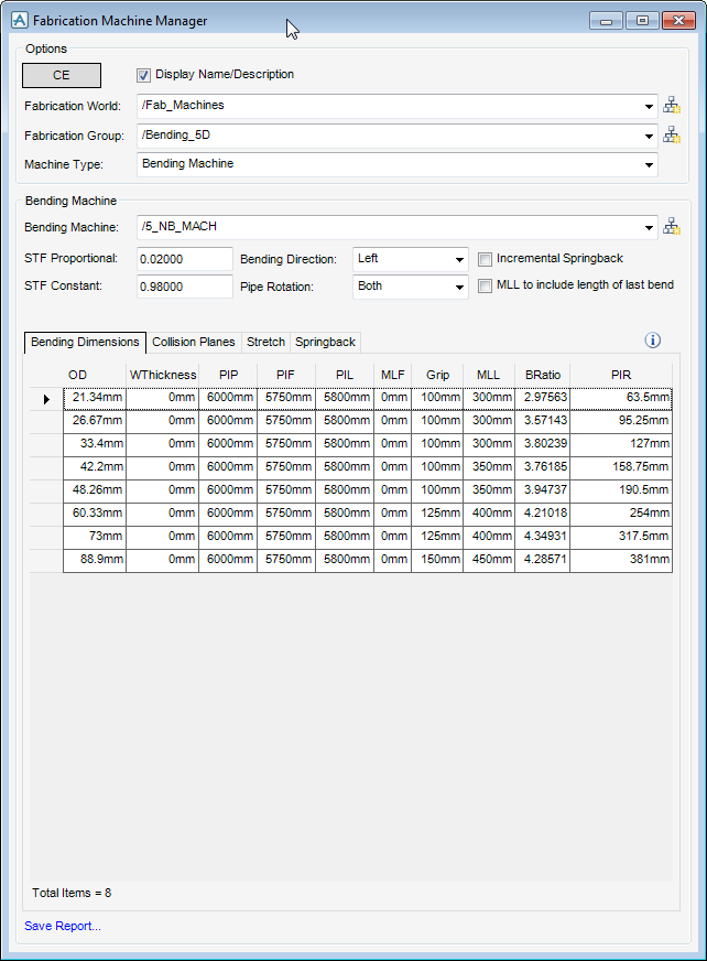
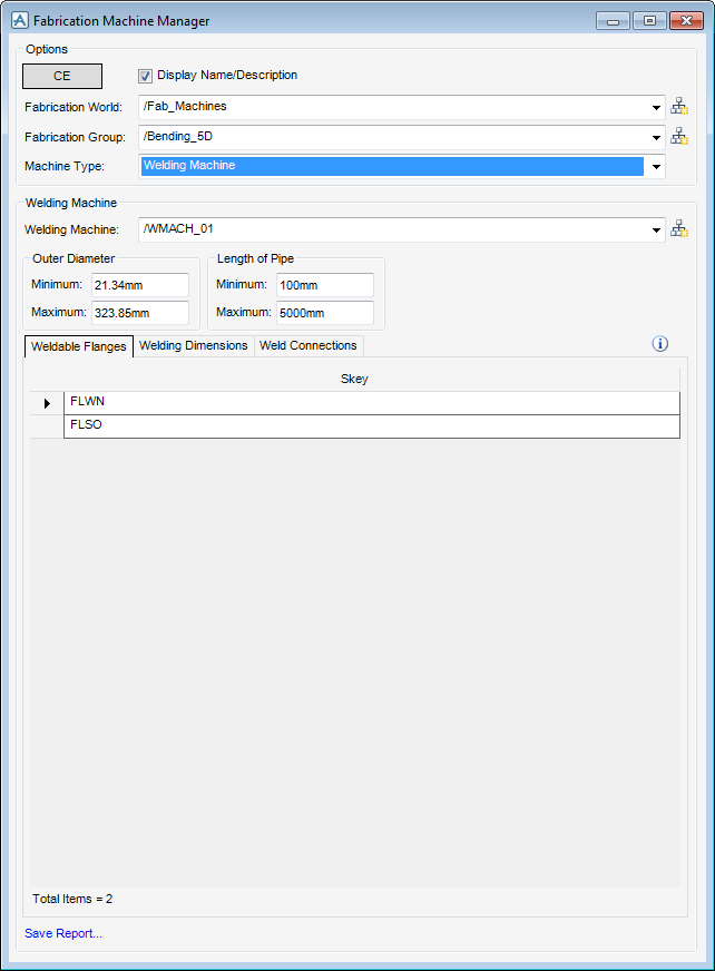
Use the Options part of the Fabrication Machine Manager window to select the element in the Model Explorer as the CE, display the name or description of the fabrication elements, select an existing fabrication world, group and machine type or create new ones.
By default, the Display Name/Description checkbox is selected populating the fabrication world, group and machine type names. To display the descriptions of these elements, select the checkbox.
|
Note:
|
Dependent upon the fabrication group selected will determine what machines and associated attributes populates the Fabrication Machine Manager window.
|
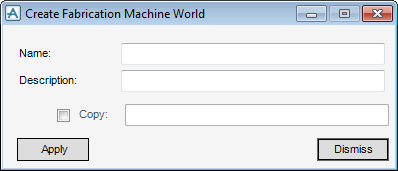
Use the Create Fabrication Machine World window to create the administrative element required.
Use the remaining part of the Fabrication Machine Manager window to create a new machine, along with attributes, view and/or edit those attributes of an existing machine.
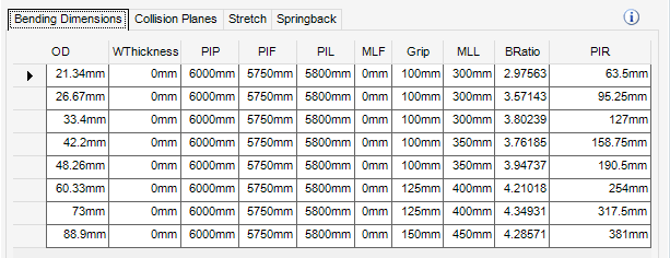
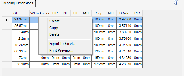
The Bending Dimensions grid is populated with the bending machine information for the selected machine:
|
•
|
By default, the Bending Dimensions tab is selected, the Bending Dimensions grid is populated with the currently selected bending machine dimensions.
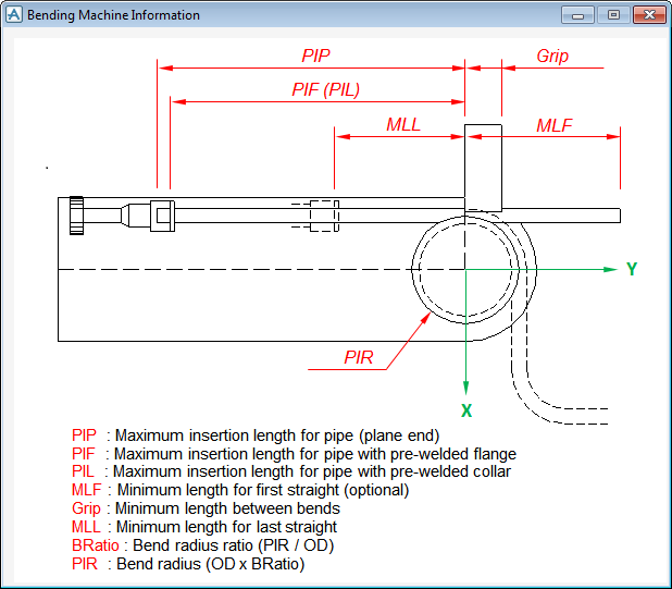
Use the information icon to display a graphical representation of the bending machine information displayed in the Bending Machine Information window. This information is also displayed in a column format in the grid, these can also be modified.
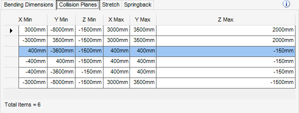
The Collision Planes grid is populated with the coordinates for the collision planes for the currently selected bending machine, a visual representation is also displayed. These coordinates can be modified.
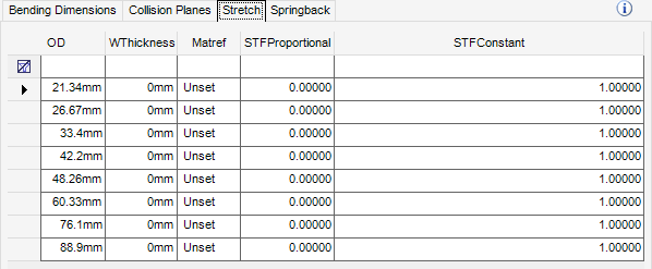
The Stretch grid is populated with the information for the currently selected bending machine, these values can be modified.
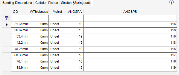
The Springback grid is populated the information used to control the accuracy of bending. Refer to Incremental Springback for further information.
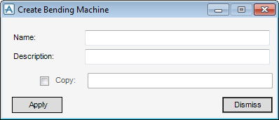
Use the Create Bending Machine window to create a new bending machine or copy an existing Bending Machine
Right-clicking within the grid on the Fabrication Machine Manager window displays a menu of commonly available options, whatever machine is selected.
|
Displays the dimension data in the Print Preview window. For a description of the Print Preview tool bar functionality, refer to Print Preview for further information.
|
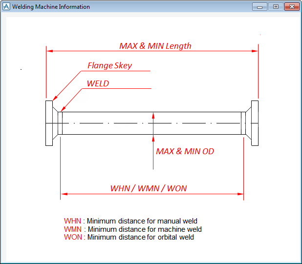
Use the information icon to display a graphical representation of the weld dimensions displayed in the Welding Machine Information window. By default, the Weldable Flanges tab is displayed.
The Weldable Flanges grid is populated with a list of flange’s suitable for use with the currently select welded machine. These can be modified and right click menu functionality is also available for selection. Refer to Grid Menu for further information.
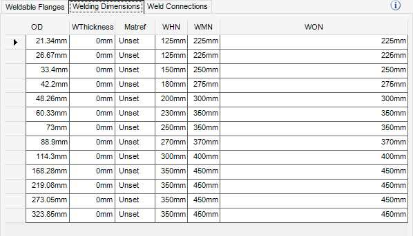
The Welding Dimensions grid is populated with the information for the currently selected welding machine. These can be modified and right click menu functionality is also available for selection. Refer to Grid Menu for further information.
The Weld Connections grid is populated with a list of the connection codes for the currently selected welding machine. These can be modified and right click menu functionality is also available for selection. Refer to Grid Menu for further information.
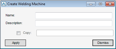
Use the Create Welding Machine window to create a new welding machine or copy an existing welding machine.
Right-click within the grid on the Fabrication Machine Manager window displays a menu of commonly available options, whatever machine is selected. Refer to Grid Menu for further information.
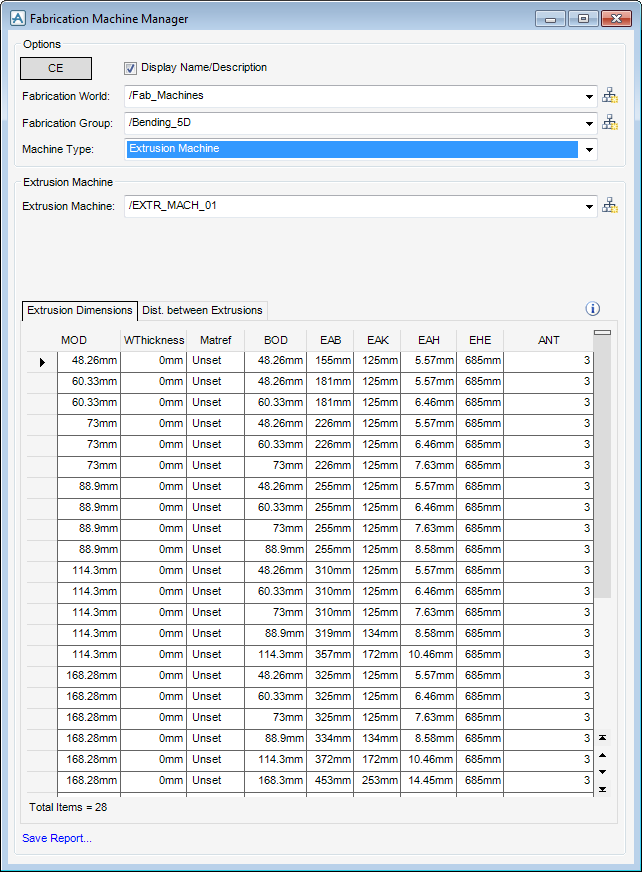
The Fabrication Machine Manager window is populated with Extrusion defaults, allows the creation of extrusions successfully.
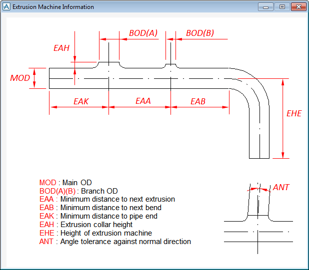
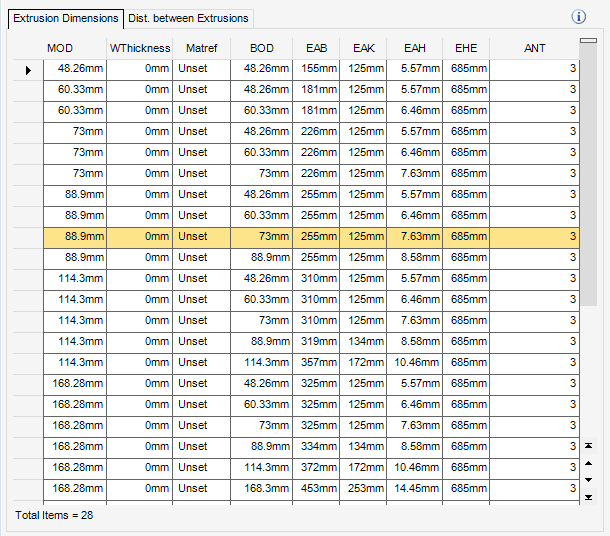
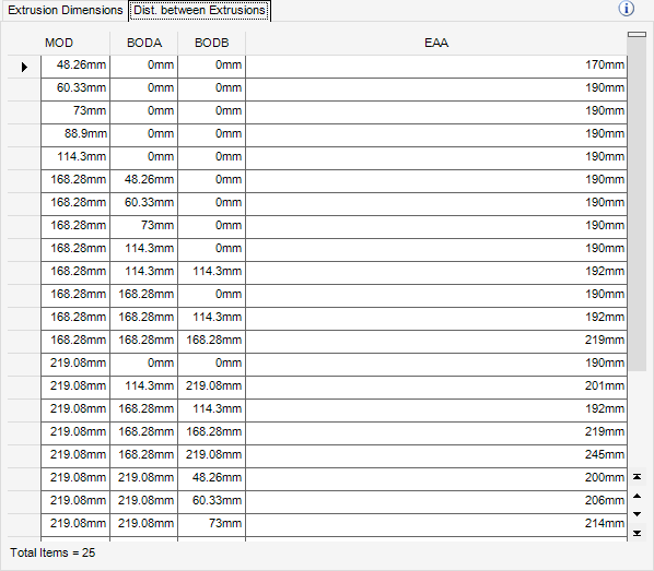
Use the information icon to display a graphical representation of the extrusion dimensions displayed in the Extrusion Machine Information window. By default, the Extrusion Dimensions tab is displayed.
The Extrusion Dimensions grid is populated with the information for the currently selected extrusion machine. These can be modified and right click menu functionality is also available for selection. Refer to Grid Menu for further information.
The Distance Between Extrusions grid is populated with the information for the currently selected welding machine. These can be modified and right click menu functionality is also available for selection. Refer to Grid Menu for further information.
Right-click within the grid on the Fabrication Machine Manager window to display a menu of commonly available options, whatever machine is selected. Refer to Grid Menu for further information.
|
Note:
|
|
Note:
|
|
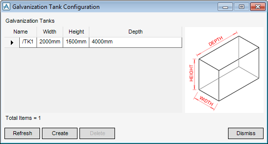
Refreshes the Galvanization Tank Configuration window.
|
|
|
Creates a new galvanisation tank, the user must enter a Name and populate the Width, Depth and Height fields.
|
|
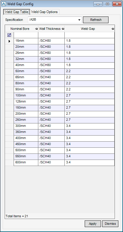
Defines the physical weld lengths for different piping specifications and weld handling information. By default, the Weld Gap Table is displayed.
|
Note:
|
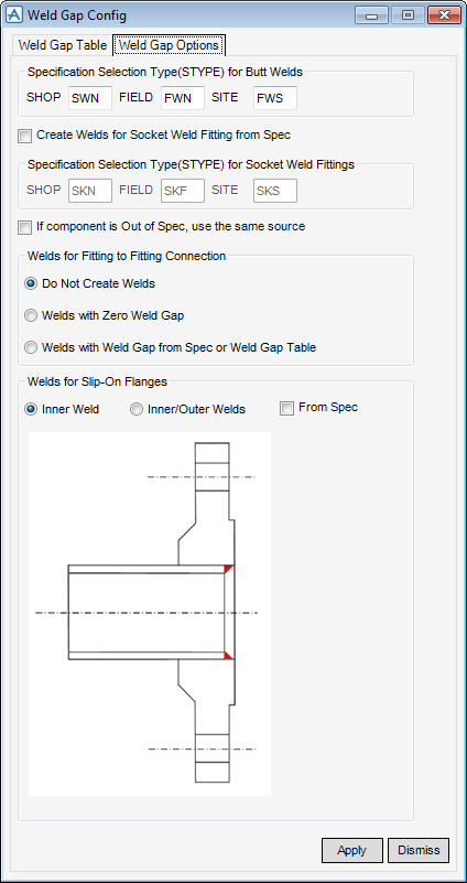
Use the Weld Gap Options part of the Weld Gap Config window to define the weld handling information.
If required, modify the values in the SHOP, FIELD and SITE fields to define the weld specification for each weld type.
Use the Create Welds for Socket Weld Fitting from Spec check box to create welds for the socket welding fittings from the specification.
If required, modify the values in the SHOP, FIELD and SITE fields to define the weld specification for each weld type.
Click to select the If component is Out of Spec, use the same source check box to use the same source if the component is out of specification.
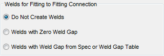
Use the Welds for Fitting to Fitting Connection part of the Weld Gap Options tab to specify the weld type for fitting welds.
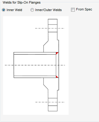
The Welds for Slip-On Flanges part of the Weld Gap Options tab, specifies the weld type for slip-on flanges.
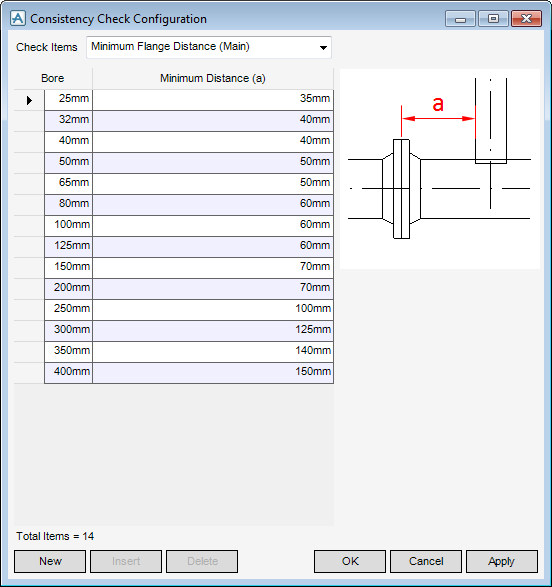
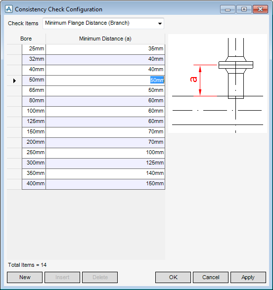
Checks pipes that are still being designed for fabrication readiness, some of the checks require configurable dimensions or minimum distances. By default, the Minimum Flange Distance (Main) check is selected. Which means the minimum distance between the branch and the next flange can be defined for the main pipe.
|
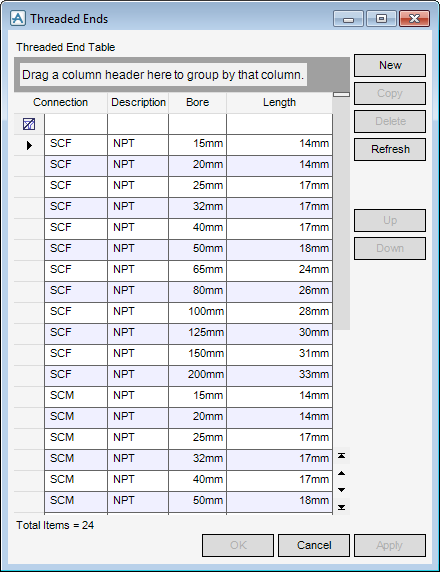
Creates a threaded end in the list of available threaded ends, populate the Connection, Description, Bore and Length fields.
|
|
|
Refreshes the Threaded Ends window.
|
|
|
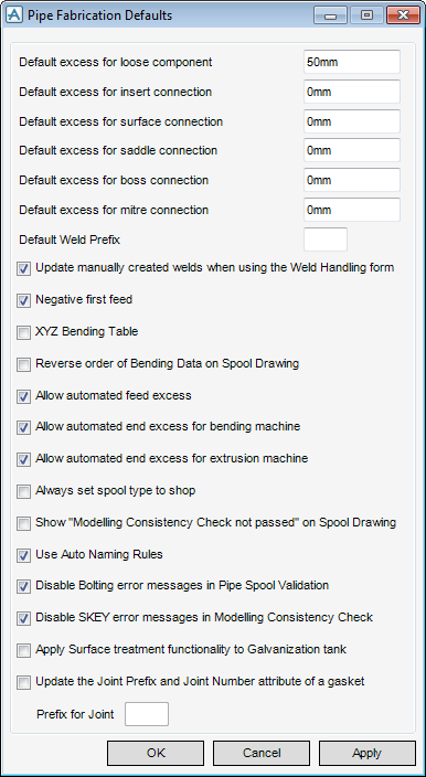
Defines the Default Weld Prefix displayed on the Weld Handling window.
|
|||
|
Defines the behaviour of welds added manually using the Pipe Component Editor window.
|
|||
|
Select the check box to use auto naming rules, refer to Autonaming for further information.
|
|||
|
Use to replace the :GALV column in the Galvanization Tank Check window with the Outside/Inside Punch Codes allocated as the surface treatment.
|
|||
|
|
Gets the FirstFeedNegative setting of the fabrication machine manager.
|
||
|
Gets a BendingMachineResult object with information about the bending machine for the last fabrication test.
|
||


