Piping
Spool Drawings
All of the tasks that a user would carry out that are associated with the creation, modification, drawing options and errors of Pipe Spool Drawings are initiated from a central Pipe Spool Drawing window which acts as a task hub.
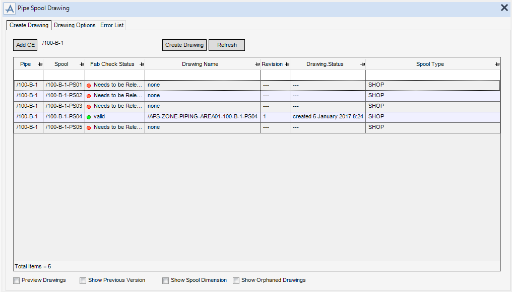
When the Pipe Spool Drawing window is opened, the application searches for valid pipe spools below the current element and loads them into the grid. To be valid for the production of pipe sketches, each pipe must be validated using the spooling and checks functionality and must be released for Fabrication. Refer to Spooling and Checks for further information.
The Create Drawing tab contains a list of available spools that displays the currently selected pipe spools together with the drawing status and revision number.
|
Refreshes the Pipe Spool Drawing window.
|
|
|
Navigates to the selected spool in the Model Explorer.
|
|
|
Removes the selected spool from the Pipe Spool Drawing window.
|
|
|
Removes all spools from the Pipe Spool Drawing window.
|
|
|
Selects all spools in the Pipe Spool Drawing window.
|
|
|
Unselects all the spools in Pipe Spool Drawing window.
|
|
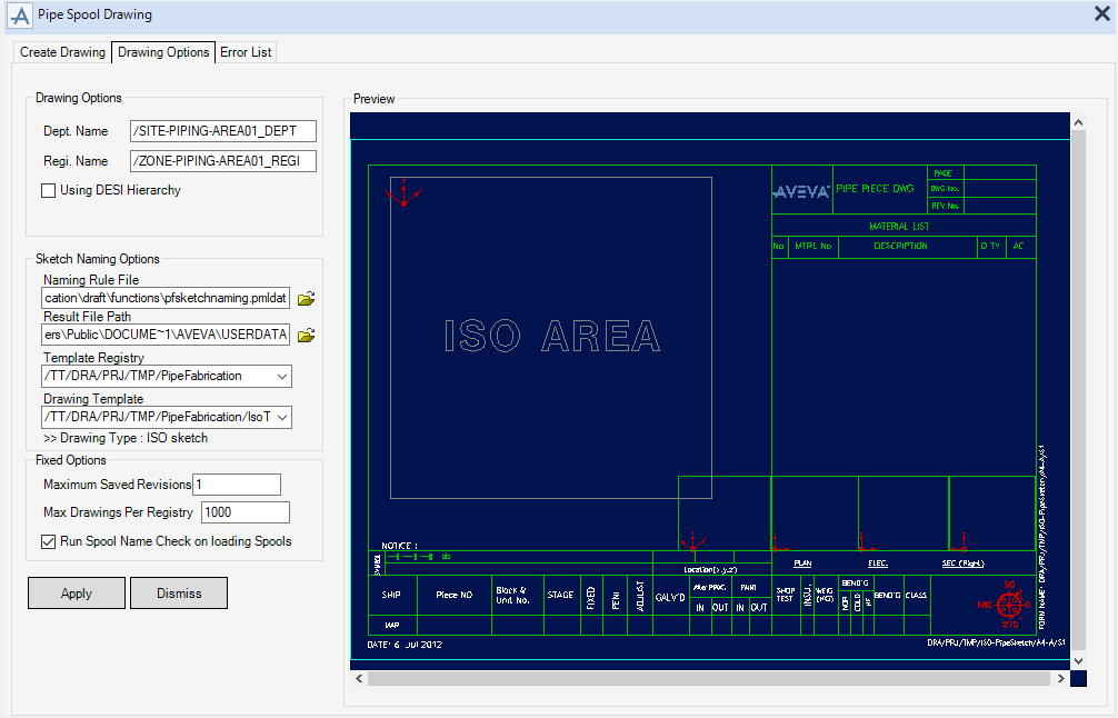
Use the functionality available for selection on the Drawing Options tab to define the options for the drawing.
The Drawing Options tab is used to set up the Drawing Departments and Registries, this must be done before drawings are produced for the first time. The selected options are saved to a file for subsequent drawings.
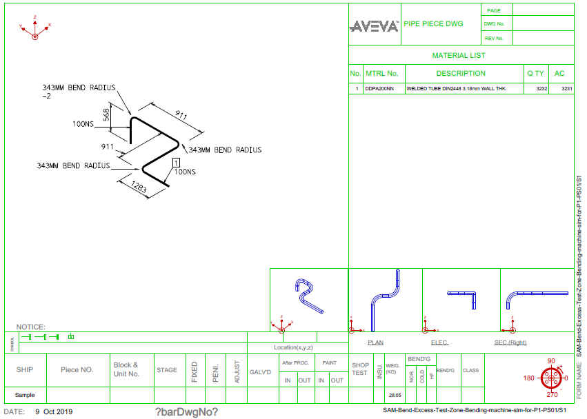
The Sketch Naming Options can be used to create various types of drawing.The example displays a drawing with an isometric overlay which is produced using ISODRAFT.
|
A preview of the drawing template displays on the right side of the Pipe Spool Drawing window.
|
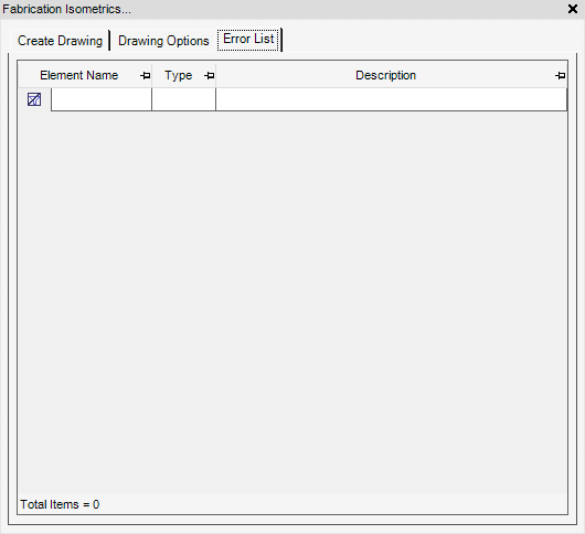
The Error List tab displays any errors encountered during the creation of the pipe spool drawing. To display the error list, select the Error List tab.
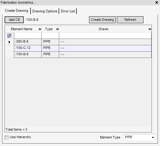
All of the tasks that a user would carry out that are associated with the creation, modification, drawing options and errors of Fabrication Isometrics are initiated from a central Fabrication Isometrics window which acts as a task hub.
The Create Drawing tab contains a list of available items that displays the currently selected elements together with the drawing status.
|
Refreshes the Fabrication Isometrics window.
|
|
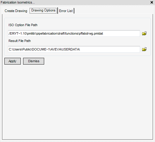
Use the Drawing Options to define the options for the drawing.
The Error List tab displays any errors encountered during the creation of the drawing. To display the error list, select the Error List tab.
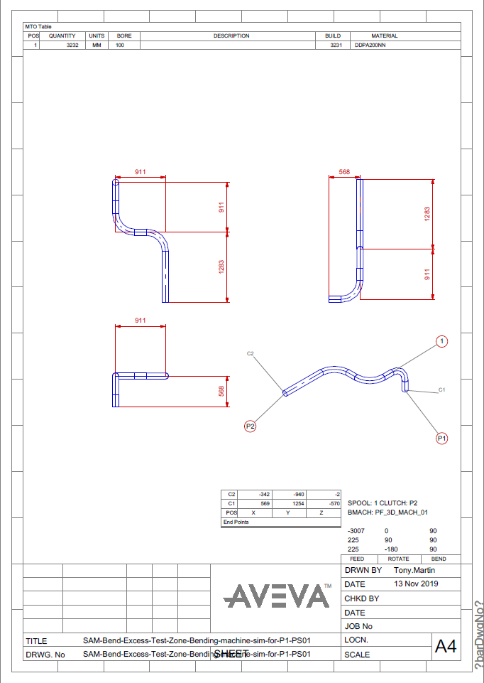
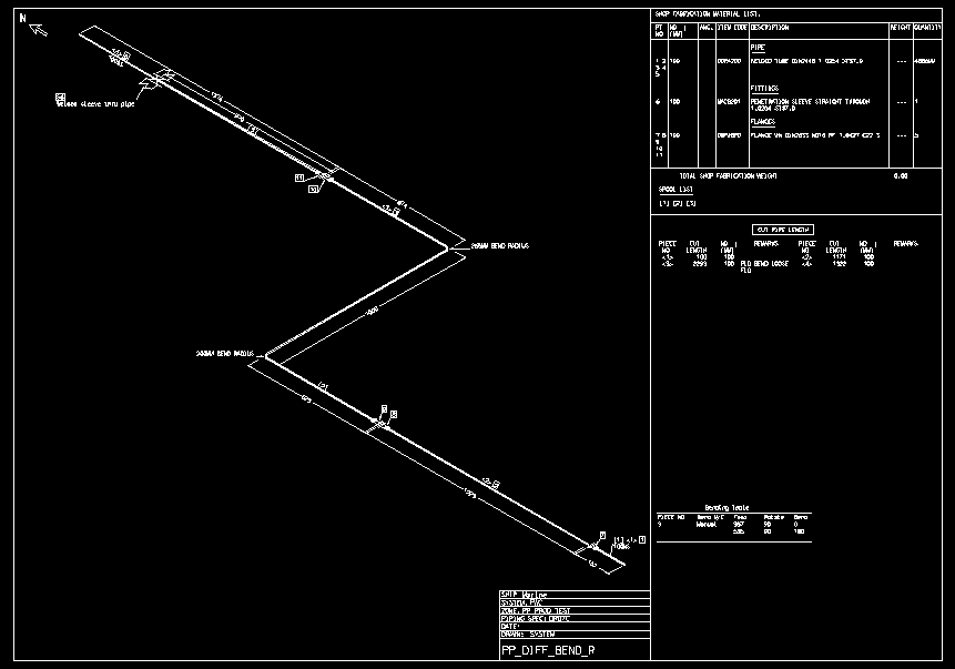
To define the Feed value, in the Bending Table, as a negative value. Refer to Defaults for further information. The Bending table is shown only for PSPOOL elements.
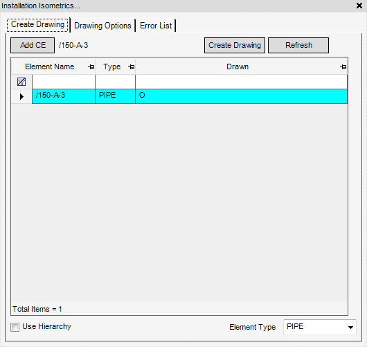
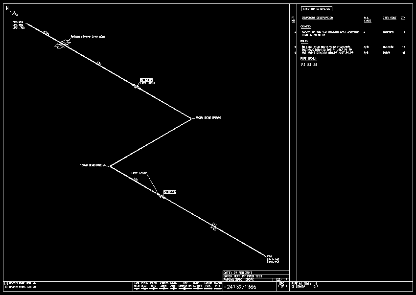
All of the tasks that a user would carry out that are associated with the creation, modification, drawing options and errors of Installation Isometrics are initiated from a central Installation isometrics window which acts as a task hub.
The functionality of the Installation Isometrics window is identical to the Fabrication Isometrics window. Refer to Fabrication Isometrics to for further information.

