Piping
Pipe Router : Automatic Pipe Route Administration
Routing Rules are special AVEVA E3D™ rules which are used to control, for example, how Pipe Router selects, positions and orientates components as Branches are routed, and also how Pipes are packed on Pipe Racks and Routing Planes.
|
Note:
|
Refer to Model Reference Manual for further information on defining rules for setting attributes.
|
The routing rules available are listed below, identified by their PURP attribute, and with a short description. The purpose is set to a four-letter code, but it sometimes displays as a more descriptive text on the AVEVA E3D™ Router windows. How each rule is applied is described in detail in How Routing Rules are Applied.
|
•
|
Selection: the elements to which the rule applies.
|
|
•
|
A Logical test which evaluates to TRUE or FALSE. For example, (ATTRIB ADIR EQ D) specifies that the arrive direction is down.
|
Rules which use logical expressions are called logical rules. A Rule which does not have a logical expression is called a real rule, because its action (see below) is a real expression.
|
•
|
The Action which AVEVA E3D™ carries out. The actions for logical rules are carried out if the Logical test evaluates to False. For example,
(AXES PP 3 IS N) orientates a valve so that the P3 axis is in the north direction. |
The Logical and Action expressions in Routing rules can call PML functions, which allows you to define much more complex logical tests and actions than can be done using simple expressions. A function is called by setting the rule action to a text string which is the name of the .pmlobj file. The file contains the object definition, followed by a method definition.
|
Refer to Pre-processing (PRPR) for further information.
|
|
|
Refer to Orientation for further information.
|
|
|
Refer to Clash Exclusion (CLEX) for further information.
|
|
|
Refer to Post-processing for further information.
|
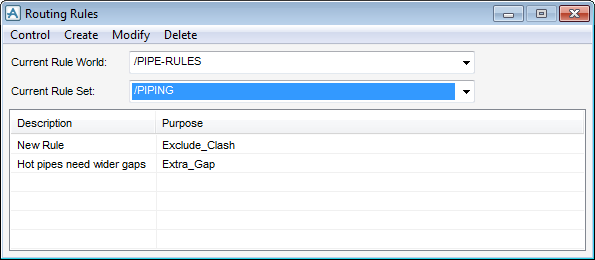
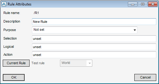
The following sections describe in detail which expressions are required by each type of rule, and how the rules are applied. Most of the examples are taken from Rules supplied with the product. To see more examples, select Settings > Routing Rules from the Pipe Router window, which displays the Routing Rules window. Select a Rule Set, then select a Rule from the list. To see the expressions in the rule, select Modify to display the Rule Attributes window.
|
•
|
|
•
|
|
•
|
The default method of changing direction, set on the Pipe Router Defaults window, is using Elbows.
The default method of changing direction, set on the Pipe Router Defaults window, is using a Rule. The rule specifies that small bore pipes change direction using Bends
|
Note:
|
The rule is only applied if you set the Change direction using option on the Pipe Router Defaults window to Rule.
|
You can omit the action by setting the Action field on the window to unset, but the result may be unpredictable, particularly if other rules are being applied, and it is not recommended. If no action exists, and component positioning is head relative, the component is moved 2/3 the distance along the leg, and then re-tested. If component positioning is tail relative, the preceding component is moved if necessary when it is positioned.
You can omit the action by setting the Action field on the window to unset, but the result may be unpredictable, particularly if other rules are being applied, and it is not recommended. If no action exists, and component positioning is tail relative, the component is moved 1/3 of the upstream distance, and then re-tested. If component positioning is head relative, the following component is moved if necessary when it is positioned.
Automatic routing along Pipe Racks is described in Create and Use Pipe Racks. In summary, Pipe Router sees a Pipe Rack as a group of routing planes. Each plane has its FUNCTION attribute set, for example to UTIL for planes which are going to route utilities pipes. You should also make sure that Branches which are routed along Pipe Racks have their PURPOSE attribute set appropriately, so that you can identify which Branches should be routed along a given plane.
Refer to Packing Methods for further information on Pipe packing methods.
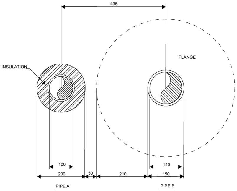
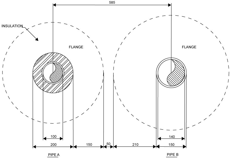
The next example uses a property of the Flange, which would be specified in a dataset:
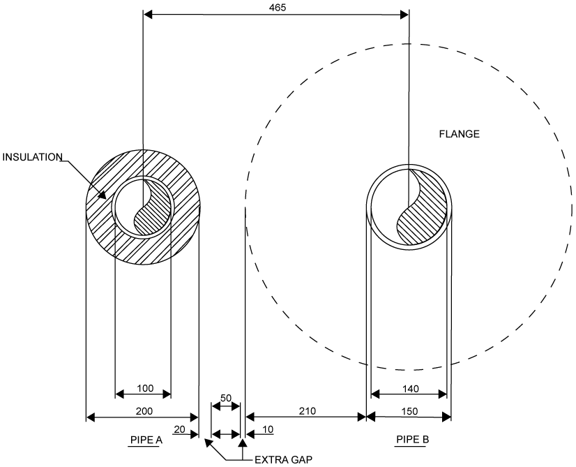
Refer to Flanges on Routing Planes for further information on how Flange widths are calculated.
A sample set of rules is provided with Pipe Router in the Sample Project. The Rule World is named /PIPES-RULES, and it owns several rule sets. The rules in the rule sets are examples which you can use to build a customised set, and do not necessarily represent good engineering practise.
From the Pipe Router window, select Settings > Routing Rules to display the Routing Rules window. Select Create > Rule World to display the Create Rule World window. In the Name box, input a name for the rule world, click OK to create the Rule World.
The rule world is created and displays in the Members List. Create a rule set within the rule world.
Make sure that at the level of the Rule World in which you want to create the rule set is selected. From the Routing Rules window, select Create > Rule Set to display the Create Rule Set window. In the Name box, input a name for the Rule Set. In the Function box, input the function of the rule set. (The function is a descriptive term which enables you and other users to identify the purpose of the rules contained within the rule set.) Click OK to create the Rule Set.
The set displays in the Members List. You can now create routing rules and store them within the rule set.
Select where the rule is to be stored by first selecting the rule world from the Current Rule World drop-down list, and then the rule set from the Current Rule Set drop-down list.
To create a new rule, select Create > Rule > New to display the Create Rule window. A new rule element (GRUL) is created in the design hierarchy.
In the Name box, input a name for the new rule element, which is the name of the rule element (GRUL) that displays in the design hierarchy.
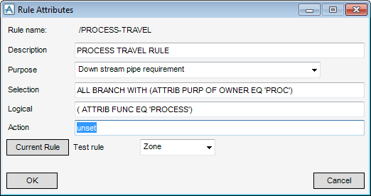
Click OK to name the new rule element, close the Create New Rule window and display the Rule Attributes window.
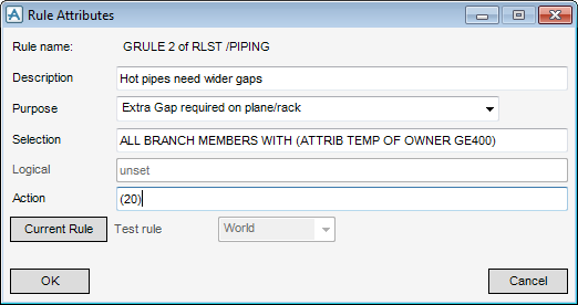
In the Description box, input a description for the rule. The description displays in the Routing Rules window.
Select a purpose for the rule from the Purpose drop-down list.
In the Selection box, input an expression. For example: ALL VALV WITH (ATTRIB STYP EQ ‘GATE’), this expression tells Pipe Router that the rule is applicable to all valves that have their attribute STYP set to GATE, that is, all gates valves.
In the Logical box, input an expression. For example: ( ATTRIB PDIR 3 EQ N ), this expression checks whether or not the direction of P3 on each gate valve is set to north. If it is, then the gate valve meets the criteria of the rule and no action is taken. If the direction of P3 is not north, then Pipe Router performs the action expression described in the next step.
In the Action box, input an expression. For example: (AXES PP 3 IS N AND AXES PL IS AXES PL OF PREV), this expression tells Pipe Router to change the direction of P3 to north, and make the leave direction the same as for the previous component.
Select the attribute of the CE, click Current Rule. The Rule Attributes window is now populated with the details for the current rule.
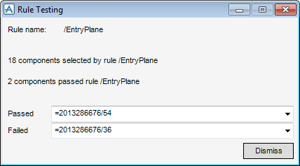
Set the extent of the test (World, Site, Zone, Pipe, from the Test Rule drop-down list, which performs the selection operation defined for the rule, then perform the logical test for each component selected, and report which components passed and which failed. The report displays in the Rules Testing window.
To copy an existing rule, from the Routing Rules window, select Create > Rule > Copy to display the Create Copy Rule window.
In the Name box, input a name for the copied element, which is the name of the rule element (GRUL) that displays in the design hierarchy.
Click OK to name the copied element and close the Create Copy Rule window and display the Rule Attributes window.
When you create a copy of a rule, the Rule Attributes displays, filled in with the details of the copied rule. You can then edit the details of the rule, which enables you to select an existing rule and use its details as the starting point for a new rule or modify the details to suit your purpose.
Edit a routing rule, using as an example the sample rules supplied in the rule set TRAVEL-RULES. The rules are modified to give a better route for the pipe rack example in Create and Use Pipe Racks.
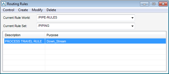
To modify a routing rule, from the Pipe Router window, select Settings > Routing Rules to display the Routing Rules window.
The Rules available are supplied in the sample project. Make sure that the Current Rule World is set to PIPE-RULES and the Current Rule Set is TRAVEL-RULES. There are three Rules supplied: a Travel Plane Rule, an Entry Plane rule and an Exit Plane rule.
To see the expressions in the Travel Rule, you must select the rule in the list and then select Modify > Rule on the Routing Rules window. The Rule Attribute window displays and is populated with the attributes for Travel Rule.
From the Rule Attributes window, note that:
|
•
|
The Selection text box contains the expression
|
|
•
|
The Logical text box contains the expression:
|
|
•
|
To see the expressions in other rules, select the rule in the list on the Routing Rules window and click Current Rule on the Rule Attributes window.
|
Select the Exit rule in the list on the Routing Rules window and click Current Rule on the Rule Attributes window. Change the Logical expression to be:
|
•
|
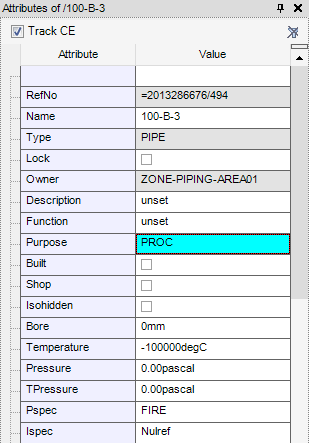
To view the pipe attributes, with the pipe selected as the CE, on the Piping tab, in the Common group, click Attributes list to display the Attributes window.
|
Press the Enter Key and the Purpose row is highlighted to indicate that the update has succeeded.
For example, the exit plane rule. Select the exit Plane rule in the list and make sure that Pipe 2001 is the Current Element. Set Test Rule to Pipe to display the Rule Testing window, which shows you that 1 Branch has been selected for the rule but 0 Plane. No Planes have been selected because there are no Planes with Function set to EXIT.
On the Modify Pipe Rack window, change the Function of the planes:
Associate the Rule with the Branches required. Select the Branch 2001/B1 on the Routing Rules window. Select Settings > Branch Rules from the menu on the AVEVA E3D™ Router window. On the Branch Rules window, set Apply rule sets to All Selected Branches. Select HIGH, and the rule is added to the window.
To delete a rule world, rule set, or routing rule, navigate to the rule world and rule set to be deleted from the Current Rule World and Current Rule Set drop-down lists. Select the rule to be deleted from the routing rules list. Select Delete > Rule World, Delete > Rule Set or Delete > Rule, as required.
|
•
|
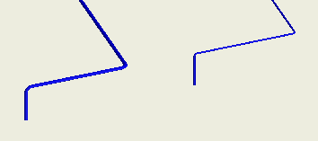
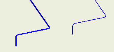
By default, Pipe Router runs pipes along Routing planes with the wall-to-wall Pipe Gap given on the Pipe Router Defaults window. Refer to Defaults for further information.
If necessary, specify an additional pipe-specific gap, for example, for very hot pipes.
|
Note:
|
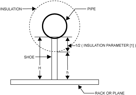
The Shoe Height is calculated from the bottom of the pipe not the insulation.
|
|
Note:
|
The P&ID file is imported by selecting Create > New Pipes From P&ID. The P&ID Import window displays.
|
Alternatively, leave both Ltail, Tdir, and Tpos unset. In this case, Pipe Router calculates the position based upon the components in the branch, and any component and tube rules that apply.
Where element can be one of the following types:
>-START PIPE /pipe_name -+------------------.
| |
‘-PSPEC pipe_spec -+-------------.
| |
‘- BORE value +--cont
| |
‘-PSPEC pipe_spec -+-------------.
| |
‘- BORE value +--cont
continued >--+- ISPEC -- insulation_spec .
| |
|- TSPEC -‑ tracing_spec ----|
| |
|- PSPEC ‑- pipe_spec -------|
| |
|- INSU ‑- value ------------|
| |
|- PRES -- value ------------|
| |
|- attribute -- value -------| .--------.
| | / |
‘----------------------------+- nl -*- branch -+- END ->
| |
|- TSPEC -‑ tracing_spec ----|
| |
|- PSPEC ‑- pipe_spec -------|
| |
|- INSU ‑- value ------------|
| |
|- PRES -- value ------------|
| |
|- attribute -- value -------| .--------.
| | / |
‘----------------------------+- nl -*- branch -+- END ->
|
INSU value
|
continued ---+-----------------------------.
| |
|- BORE integer --------------|
| |
|- PSPEC pipe_spec -----------|
| |
|- ISPEC insulation_spec -----|
| |
|- TSPEC tracing_spec --------|
| |
|- INSU insulation thickness -|
| |
|- PRES -- value -------------|
| |
|- attribute -- value --------|
| |
|- TREF /name ----------------’
|
|
| .-------<-------.
|/ |
*---- element ----'
|
‘---------------- nl -- END ->
| |
|- BORE integer --------------|
| |
|- PSPEC pipe_spec -----------|
| |
|- ISPEC insulation_spec -----|
| |
|- TSPEC tracing_spec --------|
| |
|- INSU insulation thickness -|
| |
|- PRES -- value -------------|
| |
|- attribute -- value --------|
| |
|- TREF /name ----------------’
|
|
| .-------<-------.
|/ |
*---- element ----'
|
‘---------------- nl -- END ->
where element is any of the following:
|
/pipe_name/reducer_name
|
|||
|
/pipe_name/tee_name
|
|||
|
/pipe_name/valve_name
|
|||
|
/pipe_name/vent_name
|
|||
|
/pipe_name/inst_name
|
|||
|
/pipe_name/olet_name
|
In each case, element can optionally be followed by options from one or both of the following:
>----+--- PBOre integer ---------.
| |
|--- ANgle -----------------|
| |
|--- RAdius ----------------|
| |
|--- ABOre -----------------|
| |
|--- ISPEC insulation_spec -|
| |
|--- TSPEC tracing_spec ----|
| |
|--- LBOre -----------------|
| |
|--- PREssure --------------|
| |
|--- TEMperature -----------|
| |
‘--- RATing ----------------+--- uval -->
| |
|--- ANgle -----------------|
| |
|--- RAdius ----------------|
| |
|--- ABOre -----------------|
| |
|--- ISPEC insulation_spec -|
| |
|--- TSPEC tracing_spec ----|
| |
|--- LBOre -----------------|
| |
|--- PREssure --------------|
| |
|--- TEMperature -----------|
| |
‘--- RATing ----------------+--- uval -->
>----+--- STYpe -----------------.
| |
|--- TYpe ------------------|
| |
|--- ACOnn -----------------|
| |
|--- LCOnn -----------------|
| |
|--- PCOnn integer ---------+--- word --.
| |
‘--- word ------------------+-- value --|
| |
‘-- word ---+--->
| |
|--- TYpe ------------------|
| |
|--- ACOnn -----------------|
| |
|--- LCOnn -----------------|
| |
|--- PCOnn integer ---------+--- word --.
| |
‘--- word ------------------+-- value --|
| |
‘-- word ---+--->
|
•
|
value is the new bore of the pipe for a Reducer (or enlarger), and the P3 bore for a Tee. Any change in bore along a branch can be specified by the BORE keyword. For example:
|
|
•
|
If a component is at a different bore to the rest of the pipe, for example, a reducing valve, its PBORE0 can be set. AVEVA E3D™ Router inserts a reducer automatically when routing the pipe. An example of this syntax is:
|
element TSPEC /tspec-1 ISPEC /ispec-1
START PIPE /PIPE1 PSPEC /A3B BORE 300 ISPEC /XXX INSU 100
START BRANCH /first_branch HREF VESSEL1/NOZZ1/ TREF PUMP1/NOZZ1
VALV /VALVE1 GATE
REDU /REDU1 200
TEE /TEE 200
TEE /Tee-2 PBORE3 200
VALV /VALVE2 GLOBE
CAP /CAP1 OPEN
END
START BRANCH /second_branch HREF VESSEL1/NOZZ2 TSPEC /t-spec
VALV /GATE_VALVE GATE
REDU /REDU2 CONC 200 ISPEC /I-spec TSPEC /T-spec
END
END
START PIPE /PIPE2 PSPE /A1D BORE 200 ISPEC /DDD INSU 50
START BRANCH /branch-1 HREF /NOZZ3 TREF PUMP1/NOZZ3 BORE 150
TEE /Tee3 TEE-TYPE PBORE3 50
END
START BRANCH /branch-2 HREF VESSEL1/NOZZ4 TREF PUMP1/NOZZ4
VALV /Valve-safety1 GLOBE
REDU /R-1-1 BORE 100
END
END
START BRANCH /branch-1 HREF /NOZZ3 TREF PUMP1/NOZZ3 BORE 150
TEE /Tee3 TEE-TYPE PBORE3 50
END
START BRANCH /branch-2 HREF VESSEL1/NOZZ4 TREF PUMP1/NOZZ4
VALV /Valve-safety1 GLOBE
REDU /R-1-1 BORE 100
END
END
The syntax used in Pipe Router is to allow customers to build Router into their own systems, especially batch input, and to adapt the standard Applicationware. For most users, this should not be necessary as all important functionality is available via Applicationware.
|
•
|
Avoid referring to Elbows using “ELBO n of /B1”: Pipe Router re-creates Elbows every time a Branch is re-routed, and the numbering can easily get changed.
|
|
•
|
Commands display in a combination of uppercase and lowercase letters, where the capital letters indicate the minimum abbreviation.
|
|
Note:
|
The convention does not mean that the second part of the command must be typed in lowercase letters; commands may be entered in any combination of uppercase and lowercase letters.
|
|
•
|
Command arguments display in lowercase letters. These are just descriptions of what you are required to enter. For example:
|
|
•
|
Points marked with a plus sign (+) are option junctions which allow you to input any one of the commands to the right of the junction. For example:
|
|
•
|
|
•
|
means you can type in ABC or PQR or any command allowed by the syntax given in diagram <dia> or just press Enter to get the default option.
|
|
•
|
Points marked with an asterisk (*) are loop back junctions. Command options following these may be repeated as required. For example:
|
|
•
|
means that you can enter any combination of option1 and/or option2 and/or option3, where the options can be commands, other syntax diagrams, or command arguments.
|
For a rack the first name should be an RPLG which owns at least one RPLA with PURP PREX (that is, an entry/exit plane) and at least one RPLA with PURP not set to PREX (the travel plane).
If the HREF is unset then the head must be positioned (LHEAD true) and the head of the branch is fixed. Thus the head lock is only relevant when the head is connected to the tail of another branch. If the head is fixed the tail of the connected branch is positioned where the head of this branch is, but if the head is not fixed the head of this branch is positioned at the tail of the connected branch.
|
Note:
|
PURP = PREX - Entry/exit plane

