Piping
Pipe Router
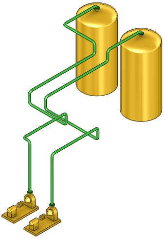
The Pipe Router utility is a rule-based tool which automatically route multiple or single pipes. If non-orthogonal pipes are required, these can be created manually, refer to Quick Pipe Routing for further information.
Constrain the route taken by the pipe(s) with the use of routing points, planes, rules and pipe racks and if required, modify the route once it has been created. Refer to Automatic Pipe Route Administration for further information.
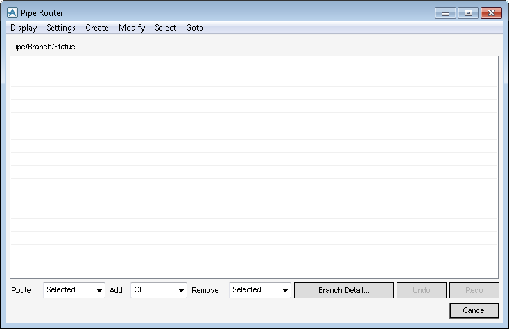
All the tasks carried out in association with the Pipe Router utility are initiated from a central Pipe Router window which acts as a task hub.
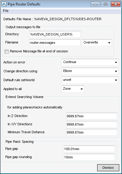
Use the File menu from the Pipe Router Defaults window, to save settings or load from settings from elsewhere, see System Administrator if new settings are required:
The Pipe Router Defaults window, contains all the tools to determine the defaults for the pipe router.
The Output messages to file fields, Directory and Filename specifies where to save and what to name the error messages file. The option to overwrite or add to the end of existing error file by selecting an option from the drop-down list is also available.
To remove the output message once a session check has been completed, click to select the Remove Message file at the end of session check box.
To specify what the Pipe Router does in the event of an error, from the Action on error drop-down list: select one of the available options.
To specify which component is used when the routing changes direction, from the Change direction using drop-down list select one of the available option.
Specify a default rule set from the Default rule set world drop-down list for all the branches created by Pipe Router which is automatically assigned as a low priority rule set. Here you or system administrator can create company and/or project specific rule sets. Refer to Routing Rules for further information.
Once the rule set has been specified define to what the rule set is applied, from the Applied to all drop-down list, select the required design hierarchy element.
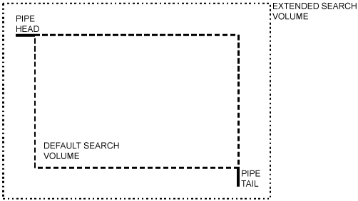
Pipe Router automatically searches for and makes use of any routing planes and pipe racks with a branch to route the pipe on. The pipe racks exist within the search volume of a branch or branches, the default search volume is the volume between the head and tail of a pipe. The search can be extended outside this volume by inputting the distances in the In Z Direction (vertical) and In X/Y Directions (horizontal) fields.
Pipe Router automatically uses a routing plane or pipe rack to route a pipe only if the distance that it travels along the plane or rack is greater than a minimum travel distance. Enter the minimum distance, in the Minimum Travel Distance field.
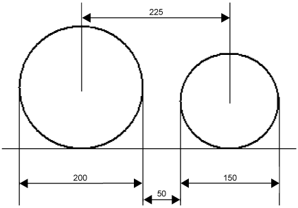
Specify the minimum Pipe gap between pipes on racks (and other planes), and also specify in the Pipe gap rounding field the extent to which the gap size is rounded, which can help minimise construction errors.
Create the pipe and branch elements in the design hierarchy and connect or position their heads and tails and define bore. If the branch contains piping components, these must be selected. Refer to New Pipe Element and Branch Element for further information.
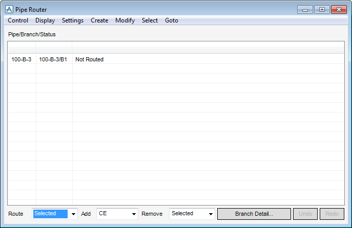
Add the pipes to the Pipe Router window, and then route the pipes, Pipes can be added individually or in groups.
By default, the Pipe Router routes pipes in the order in which they are added to the Pipe Router window. The routing order can have an effect on the route taken by pipes. Refer to Changing the Order in which Pipes are Routed for further information. Pipe Router routes the selected pipes, adding elbows, gaskets and flanges, as required.
The Pipe Router creates a route using an algorithm which minimises material cost while avoiding clashes with other objects. The algorithm has three modes of operation, described as Level 1, Level 2 and Level 3 modes. Pipe Router first searches for a route using Level 1 mode. If no clash-free Level 1 route is found, a search is made using Level 2 mode, and if no Level 2 route is found Level 3 mode is used.
Specify components in a Branch before routing, for example by importing a P&ID file as described in Import a P&ID File. Modify a routed Branch by adding other components, for example, Valves or Instruments, on the Piping tab, in the Modify group, click Component to display the Piping Component Editor window and create the components in the normal way.
Components can be locked into a given position, in which case they are not be moved, even if the Branch is re-routed. Refer to Locked Components for further information about using locked components.
If there are particular constraints that must be placed on a Branch, for example, passing through a given point or plane, use one of the techniques described in Constraining a Route.
Set rules to specify whether concentric or eccentric Reducers are used. For information about routing rules, refer to Routing Rules for further information.
How Pipe Router Routes to Free Tails
If this fails, for example, because there is a clash or a component positioning rule cannot be satisfied, then it introduces an Elbow after the constraint, before the first component. Pipe Router then positions the elbow in a direction that results in a clash-free route, and which satisfies component positioning and orientation rules.
If the Branch does not have any constraints, the position of the Tail depends on the position and orientation of the Branch Head. Often, this may be a Tee. Refer to How the Pipe Router Positions Tees for further information.
Tail direction: The TDIR attribute for a free tail is never set if the last constraint is a plane or a rack. In all other cases, TDIR is taken from the direction of the last component.
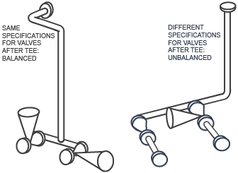
Tees which can be balanced are then positioned. Refer to Balanced Tees for further information.
Control the position of a Tee by locking it in position, or by constraining the route, using a routing point. Refer to Create a Routing Point for further information.
The Tee must be symmetric about a plane through P-arrive. The Pipe Router changes the arrive p-point to achieve this if the bores on the p-points are equal. It then checks the leave-bore and connect-bore. If the bores are equal then Pipe Router assumes that the Tee is T-shaped.
Refer to Changing the Order in which Pipes are Routed for further information.
One of the principal features of Pipe Router is its built-in rule engine. Use routing rules to control the selection, position and orientation of piping components, and to control how pipes use routing planes and pipe racks. Refer to Routing Rules for further information.
Refer to Automatic Pipe Route Administration for further information about creating your own rules.
Routing Points are points through which a pipe must pass. Specify the position of a routing point, and the direction in which a pipe arrives at and leaves a routing point. Refer to Create and Use Routing Points for further information.
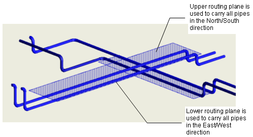
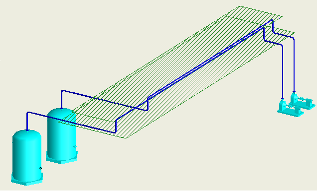
Routing planes are orthogonal planes which attract pipes to them and then guide the pipes in the direction of the plane. Routing planes are useful, for example, where to group pipes together, perhaps along a wall or ceiling. Refer to Create and Use Routing Planes for further information.
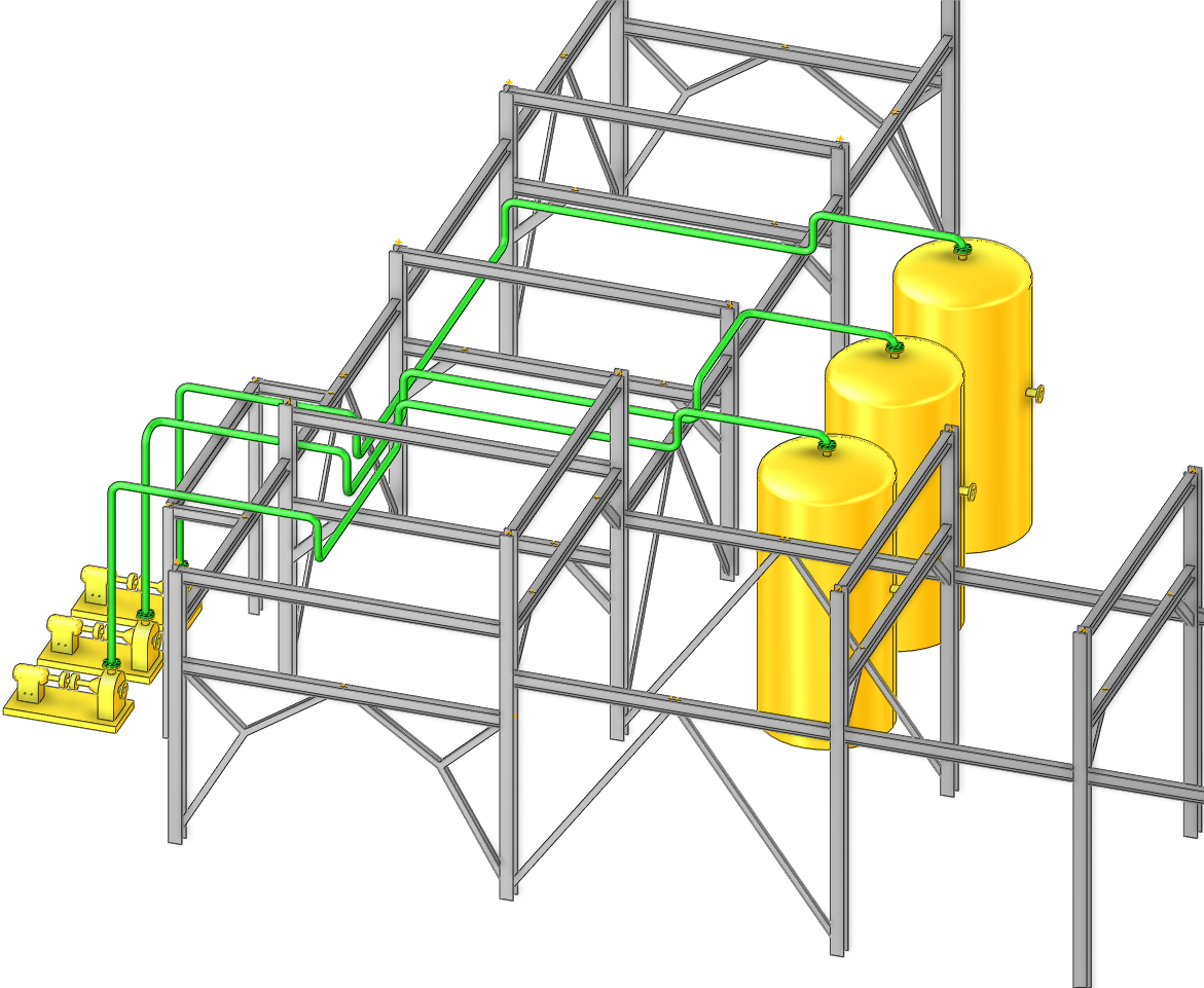
In Pipe Router, a pipe rack is composed of a group of routing planes which enables the modelling of the route used on a physical pipe rack. There are two ways in which to create a pipe rack. Create pipe racks on existing steelwork structures or model them as a group of planes.
Find the second method useful when working on a conceptual design and does not want to spend time creating steelwork structures. Once a pipe rack has been created, use routing rule to specify how different sorts of pipe run on the rack. Refer to Create and Use Pipe Racks for further information.
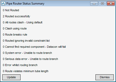
Once the pipe(s) have been routed, check the status of the branch, by selecting Display > Status Summary, the Pipe Router Status Summary window shows that two Branches have been routed successfully.
|
Note:
|
Update and Dismiss at the bottom of the Pipe Router Status Summary window can be used to update the report file or close the Pipe Router Status Summary window.
|
Pipe Router routes pipes in the order in which they are added to the Pipe Router window. However you may need to change the routing order of particular pipes to make sure that Pipe Router routes the most expensive pipes first. Or if working with pipes that are in close proximity to one another or where pipes cross paths.
Change the routing order, by selecting from a choice of options in the Modify > Routing Order > from the Pipe Router window.
|
•
|
Auto - Automatically reorders branches according to routing dependencies, that is, if a pipe is dependent on another pipe, then that pipe is routed first. Select this option, for example, after you reorder by bore.
|
|
•
|
Manual > Pipes - Manually specify the order in which the Pipe Router routes each pipe, using the Pipe Router - Reorder Pipes window.
|
|
•
|
Manual > Branches - Manually specify the order in which the Pipe Router routes each branch, using the Pipe Router - Reorder Branches window.
|
|
•
|
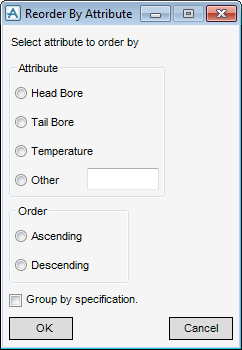
By Attribute - Reorder pipes according to particular attributes in ascending or descending order, using the Reorder by Attribute window.
|
To reorder pipes according to their specification, select Group by specification check box, the display is reordered in alphabetical order of their specification names, for example, all pipes which use the specification A150, followed by all pipes which use the specification B150, and then the other pipe specifications in the sequence. Use this option in conjunction with the attribute radio buttons.
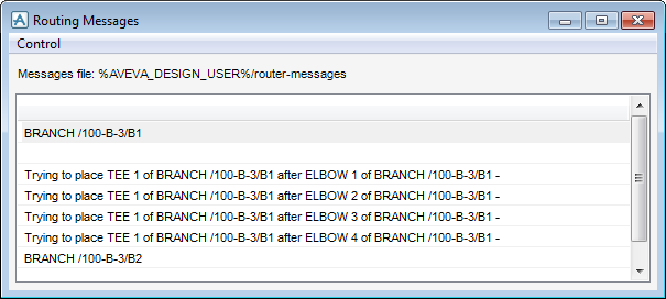
As Pipe Router routes a pipe, it examines each branch and generates a message about any routing errors that it finds. These messages can help you understand and correct errors. It can view these messages both during and after pipe routing, providing you have set up a file in which to store the messages, as described previously.
To view routing messages, select Display > Routing Messages from the Pipe Router window to display the Routing Messages window.
The Routing Messages window is empty if Pipe Router routes all pipes without any errors.
Select Control > Close to close the Routing Messages window.
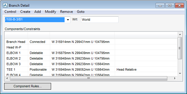
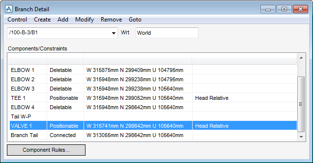
Pipe Router enables you to view details of the components and constraints in a branch using the Branch Detail window. Select options to constrain the route taken by a branch.
Select one of the routed Branches from the Pipe Router window and click Branch Detail to display the Branch Detail window, which contains details of the selected branch.
Refer to Positioning and Locking Components for more information on the contents of the Branch Detail window.
|
Note:
|
Set up rules to control the selection, positioning and orientation of components, Refer to Routing Rules for further information.
|
Pipe Router sees all piping components as deletable, positionable or locked. If the Branch Detail window displays for a Branch that has been routed by the Pipe Router, all the components are listed as deletable.
After a Branch has been routed, components can be added manually in the normal way. Select the correct element in the Branch Members list, on the Piping tab, in the Create group, click Component to display the Piping Component Editor window. These components are described as Positionable. If the Branch is re-routed, these components are not deleted, but they may be moved to fit on the new route.
The order of Positionable components in the Branch Members list is maintained, and so is their order relative to any constraints in the Branch. For example, if a Valve is added before a Locked Tee, the Valve is not be moved past the Tee.
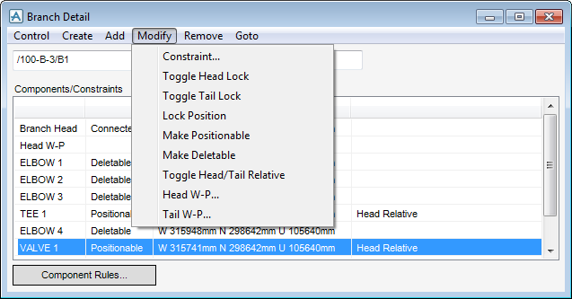
To change the status of a component, select it from the list on the Branch Detail window, and then select one of the options under the Modify menu on the window.
The choices are: Constraint, Toggle Head Lock, Toggle Tail Lock, Lock Position, Make Positionable, Make Deletable, Toggle Head/Tail Relative, Head W-P, and Tail W-P.
Each component in a branch is positioned relative to the head or tail of the branch. If a component is head relative, then Pipe Router places that component as close as possible to the head of the branch, allowing for other components and any constraints. If a component is tail relative, then that component is positioned as close as possible to the tail of the branch.
Pipe Router routes a pipe from head to tail and so all components are initially created head relative.
Change the head/tail relative property of any positionable component. Select it in the list on the Branch Detail window, and then select Modify > Toggle Head/Tail Relative.
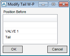
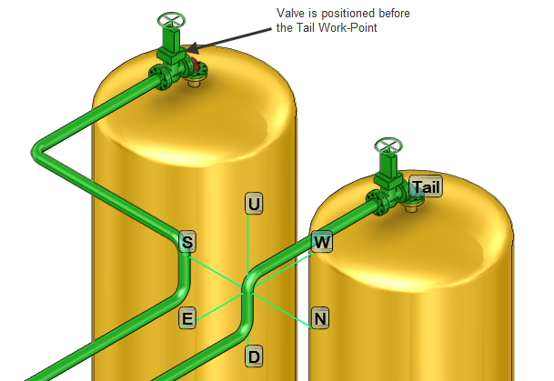
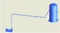
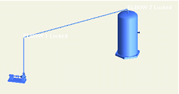
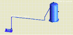
Pipe Router re-routes the Pipe from the Head Work-point to the Tail Work-point, which is now positioned before VALV 1.
Check the position of the valve, display the Branch Detail window for the branch, then scroll to the bottom of the Components/Constraints list to display the details.
To lock a component, from the Branch Detail window, select the component to be locked in position, select Modify > Lock Position.
To unlock a locked component, select Modify > Make Positionable for main piping components, or Modify > Make Deletable for Pipe Router generated components.
Lock several non-orthogonal components in a row. For example, lock two 45 degree elbows to give a non-orthogonal section of pipe and place a locked valve on this section of pipe. Pipe Router does not route any part of the Branch between the elbows, providing that straight pipe does not clash; and it adds any necessary connection components to the valve. However, the valve must be locked: if it is positionable Pipe Router routes orthogonally between the elbows.
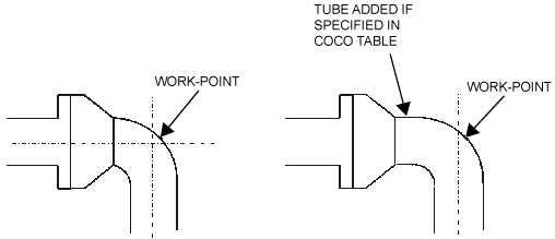
To find that components such as Olets and Stub-in Tees are positioned immediately next to another component, if the COCO tables allow. Use the Upstream and Downstream Rules provided with Pipe Router to specify minimum lengths of Tube. Refer to Routing Rules for further information about using rules.
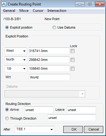
To create a routing point, select the required branch from the Pipe Router window, select Branch Detail to display the Branch Detail window. From the Branch Detail window, select Create > Routing Point to display the Create Routing Point window.
To enter the coordinates on the Create Routing Point window or use the other options available on the menu, which are similar to the normal AVEVA E3D™ positioning options. Routing points can only be positioned after positionable or locked components.
By specifying a different arrive and leave direction, a bend or elbow has to be inserted at the position of the routing point. If a change of direction is not required, select the Through Direction and specify the direction for the pipe to take at that point. If the direction is unset, Pipe Router selects the best direction to minimise the number of bends or elbows used.
There is an option on the Create Routing Point window which allows you to use an existing DATUM point as a routing point. Two branches should not use the same Datum point as a constraint since they would then clash.
To modify the position of a routing point at any time. From the Pipe Router window, select the branch to modify, click Branch Detail to display the Branch Detail window.
Select the routing point to modify from the Components/Constraints list. Select Modify > Constraint to display the Modify Routing Point window. Select one of the following options, depending on the type of modification:
Use the sample routing rules supplied with the Pipe Router, or define routing rules refer to Automatic Pipe Route Administration for further information.
|
Note:
|
Refer to Catalogue Database for further information about defining rules for setting attributes.
|
A routing rule consists of AVEVA E3D™ expressions. AVEVA E3D™ expressions are described in detail in Introduction.
For a list of AVEVA E3D™ attributes, refer to Catalogue Database for further information.
Once a rule set has been created, it can be applied to a branch. The rules then take effect on the components in the branch. From the Pipe Router window, select the branch with which you want to associate a rule set.
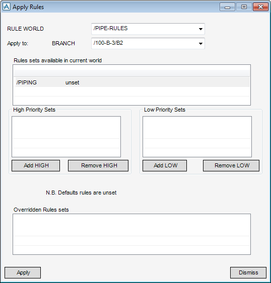
From the Pipe Router window, select Settings > Apply Rules > To Branch to display the Apply Rules to SELECTED window.
First select the rule world which contains the rule sets to apply to the branch from the RULE WORLD list, which contains all the Branches selected on the Pipe Router window. From the Rule sets available in current world list, select the rule set. The rule set can be added as high priority or low priority.
Click Add HIGH to add the rule set to the High Priority Sets list or Add LOW to add the rule set to the Low Priority Sets list. Click Apply. You must then route the branch to apply the rules.
From the Settings > Apply Rules options on the Pipe Router window applies the rule sets to a site, zone or pipe. In these cases all branches which are below them in the hierarchy also have the rule sets applied, unless they have rule sets specifically applied.
By default, Pipe Router applies all the rules in the specified sets to a branch, providing they are appropriate. However, to remove a rule from a particular component in a branch, or add one from another rule set.
To remove a rule set, first select the branch from the Pipe Router window, then select Settings > Apply Rules > To Branch to display the Apply Rules window, the rule set to be removed must be selected. Click Remove HIGH or Remove LOW as appropriate. Click Apply.
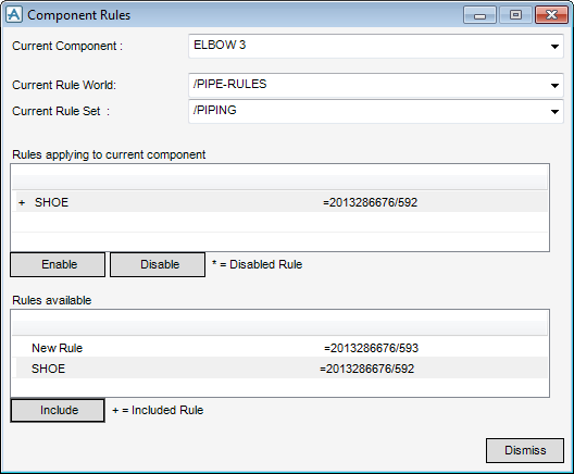
If required, apply a rule to a component from another rule world or rule set, from the Pipe Router window, select the branches to apply the rule to, click Branch Detail. From the Branch Detail window, click Component Rules to display the Component Rules window, which can be used to add additional rules from the available rule sets, or from another rule world.
From the Rules applying to current component list, select the component that the rule is applied to.
|
•
|
|
•
|
|
•
|
|
•
|
From the Rules available list, select the rule to be applied to the selected component, then click Include. The rule is added to the list of rules which apply to the component. Click Dismiss to close the Component Rules window.
Toprevent Pipe Router from applying a rule to a particular component in a branch, from the Pipe Router window, select the branch which contains the component. Click Branch Detail to display the Branch Detail window. From the Branch Detail window, select the component to be excluded from the rule. Click Component Rules to display the Component Rules window.
From the list of rules that apply to the current component, select the rule to disable from the component, then click Disable. Pipe Router places an asterisk (*) to the left of the rule description to indicate that the rule is now excluded from being used.
To re-enable a disabled rule, select the rule, then select Enable. The rule now appears in the Rules applying to current component list, preceded by a plus sign (+) indicating that it has been included.
|
Note:
|
For Pipe Router, a Pipe Rack is defined as a group of routing planes. Refer to How Pipe Router Uses a Plane for further information on Pipe Racks.
|
|
Note:
|
Allowances for shoe heights using a SHOE rule. Refer to Automatic Pipe Route Administration for further information.
|
You must not use two adjacent planes with the same travel direction and no perpendicular offset between them. For turns in the same plane, planes should touch, within 100cm, corner to corner, but not overlap. To use groups of routing planes to create Pipe Racks. Refer to Create and Use Pipe Racks for further information.
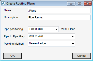
To create a routing plane make sure the STRU element is selected, from the Pipe Router window, select Create > Routing Plane to display the Create Routing Plane window, a routing plane element is created in the design hierarchy.
In the name box, input the name of the new routing plane which is the name that displays in the Members List and the Branch Detail window.
In the Description box, input the description of the routing plane, this text is not used elsewhere in AVEVA E3D™. (It may be useful for keeping a record of the plane’s purpose for future reference).
Top of pipe - Positions the top of the pipe on horizontal routing planes, or in front of vertical routing planes adjusting for any insulation. Top is the Z direction of the Plane which displays with an arrow.
|
•
|
Centre of pipe - Positions the centre of the pipe along the routing plane.
|
|
•
|
Bottom of pipe - Positions the side of the pipe below horizontal routing planes, or behind vertical routing planes, adjusting for any insulation.
|
The Pipe to Pipe Gap and Packing Method options control how Pipes are packed on the plane., refer to Pipe Packing for further information. Click OK.
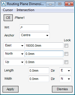
The Routing Plane Dimensions window displays.
The position from which the routing plane takes its dimensions can be changed by selecting from a choice of options in the Anchor drop-down list:
|
•
|
|
•
|
Enter the coordinates on the Routing Plane Dimension window or use the other options available on the menu, which are similar to the normal AVEVA E3D™ positioning options.
In the Length box, input the length of the plane, from the Dir drop-down list, select the direction that the pipes are to be routed along wrt to the plane.
In the Width box, input the width of the plane, then set the direction wrt to the width of the plane.
Click Apply to create the routing plane or Dismiss to discard any inputs and close the Routing Plane Dimension window.
The Routing Planes Dimensions window displays.
A vertical routing plane can be created by setting one of the Dir fields to be U or D (up or down). The up/front direction of the plane is indicated by a construction arrow in the graphical view which is drawn perpendicular to the plane. To reverse the direction, reverse either of the length or width directions, for instance from E to W.
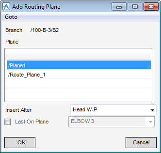
To route a branch via a routing plane, the routing plane must be added to the constraint list for the branch. From the Pipe Router window, select the branch to add the plane to, click Branch Detail to display the Branch Detail window, which contains details of the selected branch. Select Add > Routing Plane > Selection to display the Add Routing Plane window.
Where the plane is inserted can be defined by selecting from a choice of options in the Insert After drop-down list.
Click to check the Last on Plane check box to specify that positionable components are placed on the plane.
Click OK, the routing plane is added to the Components/Constraint list for the branch or Cancel to discard any changes and close the Add Routing Plane window.
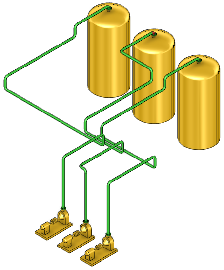
Route the branches, using the Pipe Router, the branches are routed via the routing plane.
If there are constraints in the branch, such as routing points, or locked components, an additional two horizontal or one vertical plane is searched for at the tail of the branch. These must be reachable directly from the tail and are added to the Components/Constraints list as the last constraints before the tail.
Planes are searched for in a box defined by the head and tail of the branch. The box is extended by the values specified in the Pipe Router Defaults window. Only pipes that travel along routing planes a distance greater than the Minimum Travel Distance are considered.
From the Pipe Router window, select the branch to add routing planes to, click Branch Detail. Select Add > Routing Plane > Automatically. The branches appear in the Command Input & Output window but not on the Status bar. The Components/Constraints list on the Branch Detail window are updated with the selected routing planes.
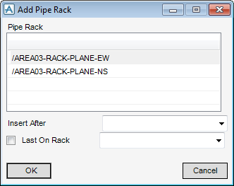
The Last on Plane check box on the Add Routing Plane window (and the Last on Rack check box on the Add Pipe Rack window) allows you to specify that positionable and locked components are placed on the plane. When it is switched on, the neighbouring list shows all the positionable and locked components in the Branch: select the one required: all the positionable and locked components after the Plane, up to and including the component given as Last on Plane, are positioned on the plane.
You can have several positionable components on a plane or rack and have more than one locked component on a rack providing they are aligned.
|
•
|
Reducers are not permitted as positionable or locked components on a plane.
|
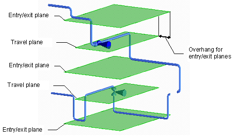
To create pipe racks with several levels, that is several travel planes. For each level of a pipe rack, a travel plane must be created to control the direction in which pipes travel along the rack and at least one entry/exit plane to make sure that pipes enter onto and exit from the rack perpendicularly, either from above or below. Each pipe rack must have at least one travel plane and at least one entry/exit plane. The direction of travel is the X direction (length) for travel planes and the Y direction (width) for entry and exit planes.
Pipe Router selects the closest pipe rack to the head in the search volume, whose direction takes the pipe closer to the tail, and providing that when using it, the pipe travels on the rack for longer than the Minimum Travel Distance as defined on the Pipe Router Defaults window.
If you are responsible for one area of a plant and a different designer is responsible for an adjacent area, a branch may run out of the first area on a pipe rack. Put the rack in the constraint list and run the branch to the area limits., by using the free tail option from the Branch Details window. A branch has a free tail when the tail is either not connected or is directly connected to another branch; and the tail is not locked.
By default, Pipe Router avoids pockets by first finding the travel plane. If the Head is above the plane, the Pipe enters from above the plane. If the Head is below the plane, the Pipe enters from below the plane. Exit from the plane is similarly controlled by the position of the Tail relative to the plane.
By default, Pipe Router runs pipes along Routing planes with the wall-to-wall Pipe Gap, with any rounding factor for the positioning, as given on the Pipe Router Defaults window. Refer to Pipe Packing for further information about how Pipes are packed on Planes and Racks.
|
•
|
Create the routing planes which model the behaviour of a pipe rack and then add the steelwork later, once you are satisfied with the route. In Pipe Router, this is referred to as a conceptual pipe rack. Refer to Create a Conceptual Pipe Rack for further information.
|
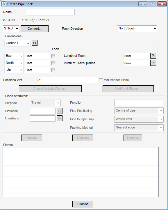
From the Pipe Router window, select Create > Pipe Rack Planes to display the Create Pipe Rack window.
In the Name box, input a name for the pipe rack, (the name of the STRU element which owns the pipe rack elements displays under the Name).
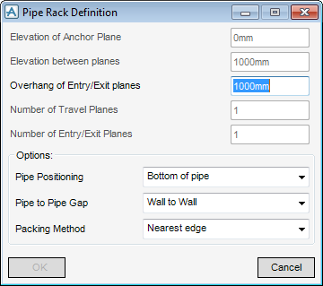
Select an element in the steelwork, click Convert to display the Pipe Rack Definition window and pick an element in the steelwork to create the rack from.
|
Note:
|
The Anchor Plane is the lowest travel plane in the rack.
|
The Overhang of Entry/Exit planes can be changed. The default value is set on the Pipe Router Defaults window.
Set any Options to apply to all planes in the Rack. Refer to Pipe Packing Defaults for further information in Pipe to Pipe Gap and Packing Method.
Click OK on the Pipe Rack Definition window, the Planes part of the Create Pipe Rack window is now populated.
Click Dismiss to discard any changes.
Pipe Router has automatically filled in the Rack Direction, and the Dimensions of the rack. The details of the Planes display in the list of Planes at the bottom of the window. The Plane attributes area of the window, the display values are those for the plane selected in the Planes list. The Plane Attributes can be edited for individual planes by changing the values in the window and then click Include to create a new plane or Replace to replace the plane selected in the list.
Select the branches from the Pipe Router window and select Modify > Branch > Add Pipe Rack > Automatically. The status line states which rack is being added to the constraints lists for the selected branches.
To manually add a pipe rack to the list of constraints for a branch, from the Pipe Router window, select the branch, select Modify > Branch > Add Pipe Rack > Selection to display the Add Pipe Rack window.
Select the required rack, click OK to add the rack to the Components/Constraint list for the selected branch or Cancel to discard any selections and close the Add Pipe Rack window.
You must then route all the branches using the Pipe Router window.
|
Note:
|
Routing rules can be used to achieve a better route: refer to Automatic Pipe Route Administration for further information.
|
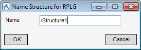
Navigate to the STRU element, from the Pipe Router window, select Create > Structure for Planes to display the Name Structure for RPLG window, a STRU element is created in the design hierarchy.
In the Name box, input the name for the structure.
Click OK to name the STRU element and close the Name Structure for RPLG window or Cancel to discard any inputs and close the Name Structure for RPLG window.
From the Pipe Router window, select Create > Pipe Rack Planes to display the Create Pipe Rack window. Define the Pipe Rack, refer to Create and Use Pipe Racks for further information on how to populate this window. Once the Pipe Rack has been created, click Create Multiple planes to display the Pipe Rack Definition window. Define the Pipe Rack, refer to Create and Use Pipe Racks for further information.
Specify the gaps between Pipes on Routing Planes, which includes Routing Planes defining Pipe Racks. The section only deals with setting values for pipe packing using the Pipe Router windows. Pipe packing can also be controlled by means of Rules, which are described in Automatic Pipe Route Administration.
By default, Pipe Router runs pipes along Routing planes with the wall-to-wall Pipe gap given on the Pipe Router Defaults window.
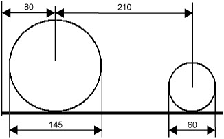
The Pipe Router Defaults window also has a Pipe gap rounding option, which makes sure that the centres of pipe are positioned at rounded coordinates relative to the edge of the routing plane. Coordinates are always rounded up. If no rounding is required, leave this value as 0. AVEVA E3D™ Router obtains values from the OD (for the current Pipe) or the geometry (for adjacent Pipes), and assume that these are consistent.
set the options on the Create Routing Plane window when Create > Routing Plane on the Pipe Router window menu is selected. You can also change the settings for an existing routing plane on the RPLA Specification window, displayed when Modify > Routing Plane > Specification on the Pipe Router window is selected.
set the options on the Pipe Rack Definition window, when you create a pipe rack. You can also change the settings for an existing Pipe Rack on the Modify Pipe Rack window, when Modify > Pipe Rack is selected on the Pipe Router window.
The flange width is the width of the default flange (for example, the flange which is obtained with a SELECT command) for the branches at their current bore, even if there are other flanges on the pipe rack.
If necessary you can change the spacing using the additional pipe-specific gap on the Pipe Router Defaults window.
The size of flanges is found using the Flange Width (FLWI) rule, which is applied to the default flange for each branch at its current bore. Refer to Automatic Pipe Route Administration for further information about routing rules.
If the P&ID system is configured so that it is capable of outputting data for use in AVEVA E3D™, you can load a P&ID file into Pipe Router. Refer to Importing Data from P&ID Files for further information about configuring P&ID output so that it is suitable for input into Pipe Router.
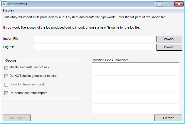
Navigate to the site or zone where to load the pipes from the P&ID. From the Pipe Router window, select Create > New Pipes from P&ID to display the Import P&ID window.
In the Import File text box, input the directory and file name of the P&ID file to load. Alternatively, click Browse to display the File Browser which contains a list of the available files, then select the required file.
If you would like to keep a copy of the log file produced during import, in the Log File box, input a file name. Alternatively, click Browse to display the File Browser which contains a list of the available files, then select the required file.
|
•
|
Modify Elements, do not ask. - Pipe Router modifies Pipes and Branches which are in both the existing model and the P&ID file. If this option is not selected, you are prompted to decide whether to modify the element or not. Minor elements (Valves, Tees and other minor components.) are made unnamed if they already exist, whether this set to on or off.
|
|
•
|
Do NOT delete generated macro - During import, a macro is created to generate all the components. Normally this file is deleted after import, but if you select this option it is kept.
|
|
•
|
Show log file after import - Displays the log file. The log file can be displayed later using the Display > Log file option on the menu at the top of the window.
|
|
•
|
Unname tees after import - If an element has a name in DESIGN, Design Manager attempts to find the name in PEGS. Tees do not exist in PEGS, and so each Tee found generates an error if this option is not selected.
|
To import the P&ID file, click Run Import.
The Modified Pipes & Branches list shows any existing Pipes and Branches that have been modified when the P&ID was read in. As far as possible, Pipe Router attempts to keep any attributes that have already been set in the model, and any constraints that have been added to Branches. However, if the P&ID file requires components to be re-ordered, elements are deleted and re-created in AVEVA E3D™, resulting in attribute settings and constraint associations to be lost.
Messages generated are also output to the Command Input & Output window, if the window displays currently. The log contains messages relating to the progress of the import operation, and any errors or warnings. In particular, the Branch Head must be positioned, if the HREF is not set.

