DRAW Reference Manual
Section Planes
:
Create and Use Planes
: Stepped Plane (SPLA)
Stepped Plane (SPLA)
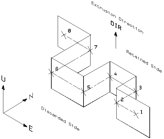
A Stepped Plane can be ‘Open’ or ‘Closed’, the type being determined by the setting of the SPLA’s GTYP attribute. The default is GTYP OPEN. GTYP CLOSED defines a closed Stepped Plane or
Enclosed Plane
. The only other attribute is DIR, which determines the Plane’s extrusion direction.
An SPLA owns WPOS elements, one per plane ‘step’, whose sole attribute is POS, the step’s 3D Design position. Specifying a 3D position automatically creates a WPOS element and sets the POS attribute. An SPLA can also own PPPT elements in order to link the plane step to a p-point or a p-line point via standard attributes DESI, NPPT, PKEY and PKDI.
The order in which the points are defined plus the direction of the plane’s extrusion determines which side of the plane is retained. A ‘handy’ rule for determining the ‘retain’ side (with PMODE STANDARD) is to hold the thumb, index finger and middle finger of the left hand mutually at right angles; if the thumb points in the extrusion direction and the index finger points towards the last step point then the middle finger points towards the retain side. A similar ‘rule’ applies for Enclosed Planes.
The SPLA can be created by a sequence of commands. For example:
NEW SPLA
DIR U
GTYP OPEN
STEP @ @ @ @
Define a series of points through which an SPLA is constructed
The STEP command invokes the cursor, which enables 3D positions or Design p-points to be identified, automatically creating WPOS or PPPT elements. DRAW imposes no limit on the number of steps, but in practice only four points can be defined by a single STEP command due to command line length restrictions. If a plane with more than four steps is required, further STEP commands enable additional points to be appended to the existing member list. The minimum number of points required to define an SPLA is 2, which has the effect of a Flat Plane.
WPOS elements can be created explicitly by command sequences, for example:
NEW WPOS
POS E120500 N236785 U0
If this syntax is used you must leave the list of WPOS elements in the correct order for the SPLA to function. The example illustrates two Stepped Planes.
If the STEP command is used then once a series of points are input a check is made to make sure correct SPLANE definition; if satisfactory then a message of the form:
Splane /name is satisfactory
is output. If the plane is
not
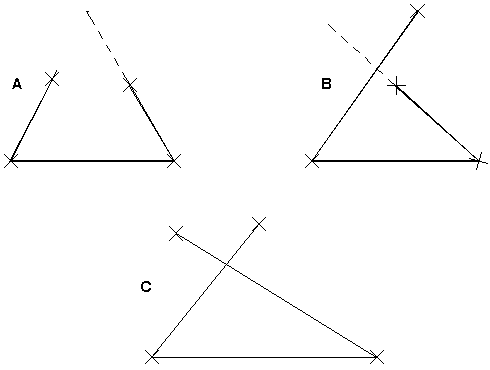
satisfactory then the message indicates what the problem is. Generally, an SPLA is incorrect if parts of the plane overlap even if extruded to infinity at the ends.
If you have defined a plane that is unsatisfactory then it must be manipulated. In examples A and B, the plane can be corrected by either reordering or repositioning one of the points or by adding a new point. Alternatively the plane can be made an enclosing type. In example C the plane can only be corrected by either reordering the points or by repositioning one or more of them. How to move points is discussed in the next Section.
1974 to current year.
AVEVA Solutions Limited and its subsidiaries. All rights reserved.