Common Functionality
Design Aids : Reference Grids : Create Rectangular Tower Reference Grid
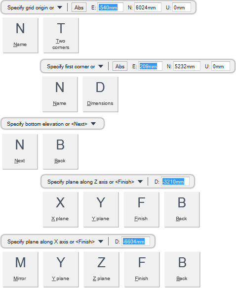
You are prompted to Specify grid origin or
Input values in the dimension fields and press Enter or click to identify the grid origin position.
You are then prompted to Specify bottom dimensions
Input values in the dimension fields and press Enter or click to identify the bottom dimensions.
You are then prompted to Specify bottom elevation or <Next>
Click the sphere grip and input a value in the dimension field and press Enter or click to identify the bottom elevation of the grid.
You are then prompted to Specify top dimensions or
Input values in the dimension fields and press Enter or click to identify the top dimensions of the grid.
You are then prompted to Specify Alignment or <Next>
Click the sphere grip and input values in the dimension fields and press Enter or click to identify the alignment of the top of the grid measured as an offset distance from the centre.
You are then prompted to Specify Alignment or <Next>
You are then prompted to Specify tower height or
Input a dimensional value in the field and press Enter or click to identify the grid height.
You are then prompted to Specify plane along Z axis or <Finish>
Input a dimensional value in the field and press Enter or click to identify a plane position along the Z axis. All elevation plane positions along the Z axis are measured from the grid origin.
You are then prompted to Specify plane along X axis or <Finish>
Input a dimensional value in the field and press Enter or click to identify a plane position along the X axis.
You are then prompted to Specify plane along Y axis or <Finish>
Input a dimensional value in the field and press Enter or click to identify a plane position along the Y axis.
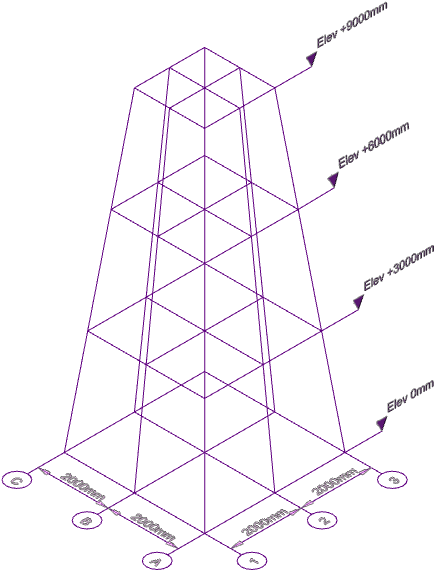
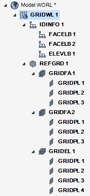
Input F at the prompt and press Enter to end the command. A grid is created with specified planes and displays in the 3D view.
Throughout the grid creation process you can press ESC to cancel the command. Additional functionality is also available.
|
Press the down arrow key and select Name to define the grid name.
You are prompted to Grid name
Input a unique name in the field and press Enter to name the grid.
|
|
|
Press the down arrow key and select Two corners to define the dimensions of the bottom or the top of the grid by specifying two corner points.
|
|
|
Press the down arrow key and select Dimensions to define the dimensions of the bottom or the top of the grid by specifying a dimension point measured from the grid origin.
|
|
|
Press the down arrow key and select Next to proceed to the next grid creation process.
|
|
|
Press the down arrow key and select Back to undo the last action.
|
|
|
Press the down arrow key and select X plane to create a grid plane along the X axis of the grid.
You are prompted to Specify plane along X axis or <Finish>
Input a dimensional value in the field and press Enter or click to identify a plane position along the X axis.
|
|
|
Press the down arrow key and select Y plane to create a grid plane along the Y axis of the grid.
You are prompted to Specify plane along Y axis or <Finish>
Input a dimensional value in the field and press Enter or click to identify a plane position along the Y axis.
|
|
|
Press the down arrow key and select Finish to end the command.
|
|
|
Press the down arrow key and select Mirror to create two grid planes mirrored from the grid origin along the X or Y axis.
|
|
|
Press the down arrow key and select Z plane to create the Z axis of the grid.
You are prompted to Specify Step along Z axis or <Finish>
Input a dimensional value in the field and press Enter or click to identify a plane position along the Z axis.
|
|


