Diagrams
User Guide
Before shapes can be imported to a stencil using the Import Shape Wizard, they will have to be created using MS Visio tools. It is highly recommended that the user creating shapes has a good knowledge of MS Visio and is familiar with how Visio shapes works before proceeding to create Diagrams shapes. MS Visio offers many possibilities for creation of smart shapes with different kinds of behaviour. We recommend that this is used sparingly and with consideration, as complex shape behaviour can result in reduced performance and also interact with the Diagrams application code in a way that can give unexpected errors. A few examples of useable behaviour are described below.
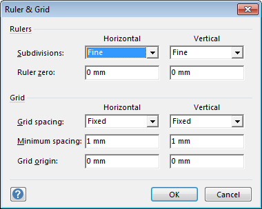
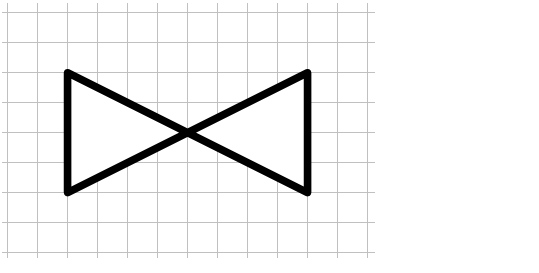
When drawing the shape, it is recommended to use the same grid setting that will apply when the shape will be used in the drawing, thereby avoiding alignment and snapping problems. To minimize the risk for mistakes when different zoom settings are used, the grid can be set to Fixed. A suitable grid size is suggested to be 1 mm. The Ruler & Grid dialogue is available from the button next to the Show group label on the View Tab.
|
Figure 3:4.
|
Connection points can be added to shapes by using the Connection Point Tool available on the dropdown for connector tool in the Standard toolbar.
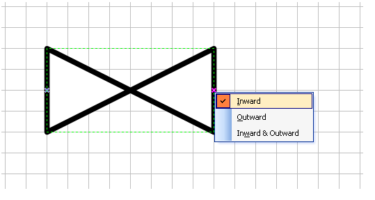
To add connection points, Ctrl+Click using this tool. For inline pipe/HVAC parts, the order in which connection points are added is relevant, as the first added connection point will correspond to ppoint 1 on the catalogue item. When an inline fitting is connected, Arrive and Leave are resolved depending on the connections. I.e. if conn 1 is connected to Leave of another fitting during define, conn 1 will be Arrive and vice versa. If it is not connected when defined, Arrive and Leave will default to 1 and 2. The direction of the connection points can be changed by right clicking on a connection point and selecting Inward, Outward or Inward & Outward.
|
Note:
|
When grouping shapes, use the Group command rather than Convert to group, as the former works better with the Diagrams application.
|
|
4.
|
Access the Shape Sheet of the group (available on the right click menu).
|
|
5.
|
If there is not any Controls section, create a new (Right click > Insert section). The newly created control should be named Attach.
|
To refer to the instrument shape, its ID should be used. It can be found in the Special format window accessible from Format > Special in the shape context menu or from the main menu.
- 1 for the rectangle shape representing label or offline instrument (Sheet.1 should be used in formulas referring to the shape)
|
8.
|
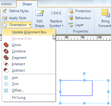
Now the alignment box of the shape should be adjusted to contain the instrument (or label) shape only. In order to do this, Attach control should be brought to inside the rectangle, so the attachment line is hidden. After that the Update Alignment Box command should be issued for the group.
|
|
11.
|
The last thing to do is to make sure that the text of the created shape will be displayed in front. To do this please make sure that Group data is set to "" in the Behaviour window accessible from Shape Tab > Properties > Behaviour:
|
|
Note:
|
The above example will allow for creating a shape with desired behaviour only before Import Shape is executed on the shape. It is because of the need to group shapes to achieve attachment line functionality.
|


