Concrete Building Design
User Guide
Concrete Building Design : Beams and Columns : Create Curved Beam
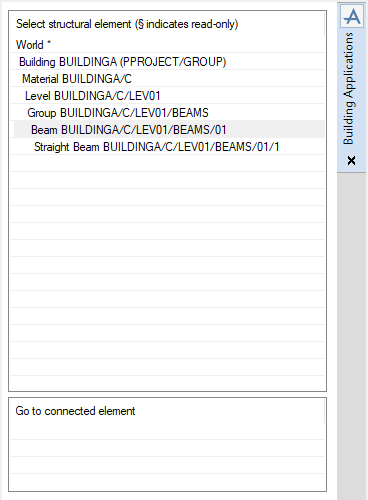
From the Select Structural Element pane of the Building Applications window, make sure that the Beam element is the CE.
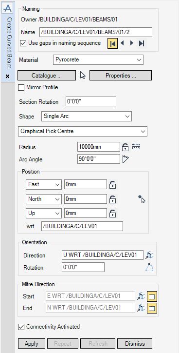
The functionality of this window is virtually identical to the Create Beam window, with the following exceptions:
|
•
|
|
•
|
The section profile that is applied to the curved beam can be mirrored. By default, the Mirror Profile checkbox is clear, to mirror the section profile select the Mirror Profile checkbox.
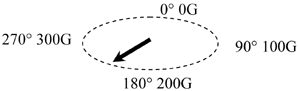
By default the section rotation is 0°0’0’’, in Section Rotation enter the rotation angle in one of the following formats:
|
•
|
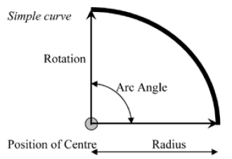
In the Shape drop-down list select from either Single Arc, the single arc option allows the user to create a single-arched shaped beam in an angle range of 0° and 360°.
The user can pick the position of curves, start points and end points of curved beam elements in the 3D graphical view. From the Create Curved Beam window, from the Shape drop-down list, select:
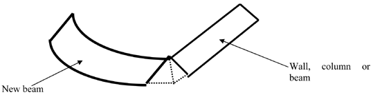
Graphical Pick Centre - Positions the centre of the single arc on an existing element in the design, the user is prompted to Graphical Pick Centre (Snap) WP Snap:
Graphical Pick Start - Picks the start of the single arc on an existing element in the design, the user is prompted to Pick Start (Snap) WP Snap: Once the selection has been made the rotation and angle are adjusted for the new start of the curve. If the radius is locked, the start position is adjusted to use the current radius. Otherwise, the end position is adjusted to use the new radius.
Graphical Pick End - Picks the end of the single arc on an existing element in the design, the user is prompted to Pick End (Snap) WP Snap: Once the selection has been made the rotation and angle are adjusted for the new end of the curve. If the radius is locked, the end position is adjusted to use the current radius. Otherwise, the start position is adjusted to use the new radius.
Graphical Pick Arc - Picks an existing panel vertex (PAVE) to establish the geometry (centre, start, end) of a single arc beam. The user is prompted to Pick PAVE:
|
Note:
|
The Graphically Pick Arc requires the PAVE to have a radius greater than or equal to half the profile width for the geometry to display. If the radius is smaller, then the geometry is rendered invalid and is not displayed.
|
If graphical pick functionality is not required, for example: precise dimensions have to be entered. The user can enter the dimensions into the Radius and Arc Angle fields from the Create Curved Beam window.
The Radius textbox displays the radius of single-arced shaped beam. To lock or unlock the radius value click Radius locked.
|
•
|
Typing a radius and clicking Enter.
|
|
•
|
Clicking Measure Length and graphically selecting existing elements to establish the radius.
|
The Arc Angle textbox displays the arc angle of a single arc shaped beam ranging from 0‑360 degrees. To populate it, type a value for the arc angle then press Enter. Arc angles can be entered in any of the following formats:
Alternatively, click Pick Arc Angle to invoke the Positioning Control window, allowing the user to make graphical selections of existing elements to establish the arc angle.
The Position section of the window is used to establish the centre position of a single-arced shaped beam. It can be populated several ways:
|
•
|
Click Graphical Pick Start to invoke the Positioning Control window to graphically pick the position. The co-ordinates are populated automatically.
|
|
•
|
Alternatively, the first two methods can be combined by utilising the padlocks. Click Coordinate locked to unlock a value or click Coordinate unlocked to lock the value. A locked value is displayed in grey.
|
|
•
|
Click Pick Elevation to invoke the Positioning Control window to graphically pick an existing element to establish the up/down co-ordinate.
|
The Orientation section of the window is used to establish the Direction and Rotation angle of the beam.
The Direction textbox displays the direction of the beam (defined from the start to the end positions).
The Pick surface or edge to define direction allows the user to graphically pick the face or edge of an existing element.
The Rotation textbox displays the rotation angle of the curved beam. To populate it type a value for the Rotation angle then click Enter. Rotation angles can be entered in the same formats as Arc Angles.
Alternatively, click Rotate angle using two picks to invoke the Positioning Control window, allowing the user to make graphical selections of existing elements to establish the rotation angle.
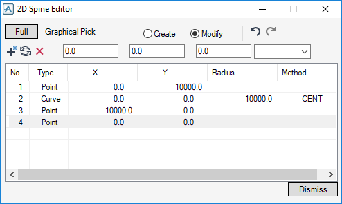
To define a complex curve, the 2D Editor must be run using the Shape drop-down list. The curved beam is created and the Modification window replaces the Creation window.
Click Apply to create the curved beam. The curved beam Modification window replaces the Creation window. If the option is greyed out, enter a valid name in the Name field to activate it.
To cancel the creation of the curved beam, click Dismiss. If the user navigates to another element, the window closes automatically.
|
Note:
|
It is also possible to create a curved beam with AVEVA E3D™ using the Sections application. On the Sections tab, in the Create group, click Curved.
|