DRAW Administrator Guide
Area Based Automatic Drawing Production : Create and Modify Template Drawings
|
•
|
Variants can only be selected from the existing drawing list on the Process Drawings Control window.
|
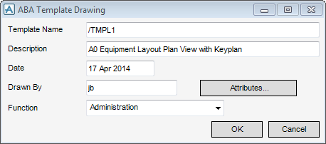
Input a suitable name for the template in the Name field.
Input a suitable description for the template in the Description field.
The value for the Date field is automatically set to the current date.
The Drawn By field is automatically populated with the login name of the administrator. The login name is taken from the operating system, not the base product.
To modify the ABA template, click Attributes to display the Drawing Template Attributes window. Refer to Drawing Template Attributes for further information.
Select the required function from the Function drop-down list. The function of the drawing is used by the drawing selection mechanism to separate different template types during creation. It is also used by the auto-numbering functionality.
Click OK to display the ABA Template Sheet window. Refer to Create ABA Template Sheet for further information
The Name field displays the name of the drawing template.
On the Size & Units tab, you must specify its dimensions, either explicitly in the Width and Height fields, or by selecting a standard sheet size from the drop-down list.
Precision allows you to define the precision that is required for both linear and angular data. Four values of precision can be stored, for metric (decimal) values, imperial decimal values, imperial fractional values, and angles. By default, these four values are 0, 1, 32 and 1 respectively. Angles are stored decimally, to the nearest whole number of degrees, to the nearest minute, or to the nearest second by selecting an option from the drop-down list.
The Intelligent Text tab is used to select an output format for the positional code words used to request the position of certain elements.These expand to a string providing the location expressed in the ENU (East North Up) coordinate system, or as a purely numerical output (Numbers only).
To accomplish this, two attributes are provided for a number of elements in the DRAW database (including DEPT, REGI, DRWG, SHEE, VIEW, LAYE). The setting of these attributes determines the output format used by the positional code words, and are determined by the selection made in the Intelligent Text tab. The same output format is used throughout a given layer.
The Pens tab allows you to set the line colour and style.
Standard options of line colour and style are set explicitly by selecting system-defined settings from the colour, line-pattern and thickness drop-down lists. Click Pick to display the Pick a Colour window. The functionality of the Pick a Colour window is explained, refer to Colour for further information.
To select a user-defined style, click Select to display the User-defined linear styles window. A style table is selected and then a selection is made from the list of styles. After selecting a user defined style, the check box is ticked by default. You can de-select this check box to use a system defined style. The functionality of the User-defined linear styles window is explained, refer to User-Defined Linear Styles for further information.
If you click Select next to Hatch Pattern, the User-defined fill styles window displays. The functionality of the User-defined fill styles window is identical to the User-defined linear styles window. Refer to User-Defined Linear Styles for further information.
You can set Miscellaneous attributes:
Click Apply to modify the drawing template attributes or Cancel to discard any changes and close the Drawing Template Attributes window.
By default, the ABA Template Sheet window displays when OK is clicked on the ABA Template Drawing window. Refer to Create ABA Template Drawing for further information.
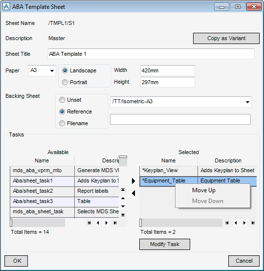
To create a variant of the master, click Copy as Variant. The current element is changed to the variant and is only available during a modify phase.
Input a suitable title for the sheet in the Sheet Title field.
Select the paper size for the sheet using the Paper drop-down list.
Select the Unset option button to specify that no Backing Sheet is used.
To select a BACK element as the Backing Sheet, select the Reference option button and select the BACK element from the drop-down list.
To select a .plt file as the Backing Sheet, Select the Filename option button and input the path of the required file in the field.
By default the Name and Description elements in the Available and Selected lists are sorted alpha numerically (A-Z, 0-9). To reverse the order, click the column header of the relevant list.
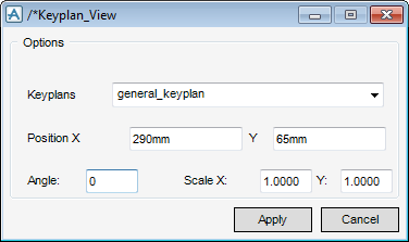
To modify the currently selected task in the Selected list, click Modify Task to display the default modify window. For example, if the *Keyplan_View task is selected the /*Keyplan_View window displays.
Select the required keyplan from the Keyplans drop-down list.
Input the keyplan angle in the Angle field.
Click Apply to confirm the modifications or Cancel to discard any changes and close the modify window.
Once the sheet is configured correctly, click OK and the Template View window appears. Refer to Create and Modify ABA Template View for further information.
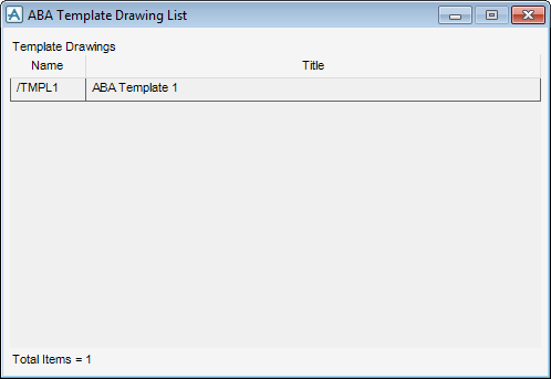
Select the template drawing to modify. By default the ABA Template Drawing window displays. Refer to Create ABA Template Drawing for further information.
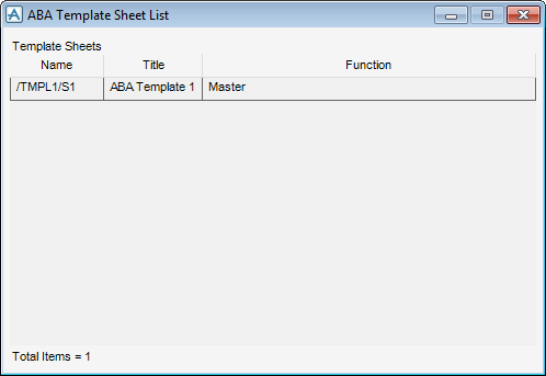
Select the template sheet to modify. By default, the Template Sheet window displays. You can modify the template sheet as required. Refer to Create ABA Template Drawing for further information.

