Structural Design
User Guide
Walls and Floors Tools : Trace
On the WALLS AND FLOORS tab, in the Tools group, click Trace to display the Boundary Tracing window.
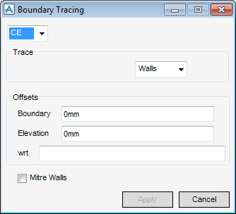
From the Boundary Tracing window, select CE, or select Pick. The user is prompted to ‘Pick Element for Boundary Tracing:’ The name of the selected element is displayed in the Boundary Tracing window.
From the Trace pane of the Boundary Trace window, select the type of element to be created - Walls, Floor or Screed.
In the Offsets pane of the Boundary Tracing window, the user must now input the required position of the new element:
Boundary positions the edges of the new element relative to the edges of the traced element. A positive boundary offset positions the new edges outside the traced boundary, a negative boundary offset positions the new edges inside the traced boundary.
Elevation positions the vertical position of the new element.
Mitre Walls checkbox is only available when the element to be traced is a wall element, the functionality allows the user to determine if junctions between the walls are to be mitred.
Click Apply to trace the boundary.
A confirmation box is displayed, click Yes to retain the boundary.
Click No to abandon the trace.