Structural Design
User Guide
Sections : Ring section
On the SECTIONS tab, in the Create group, click Create Sections, select Curved to display the Curved Section window.
All the tasks that the user would carry out with the creation of a ring section are initiated from a central Curved Section window which acts as a task hub.
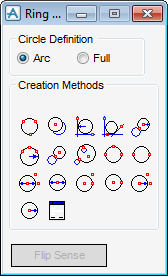
The user must first state whether the ring section is to be an arc section or full circle section. From the Circle Definition part of the Ring window, click Arc or Full.
To create a ring section, the user can select one of 17 creation methods from the Create Methods part of the Ring window.
|
|
If required the user can use the functionality displayed in the Positioning Control window.
The user is prompted to ‘Define ring section first point Distance[0]) Snap:’
Once the first selection has been made, the user is prompted to Define ring section second point (Distance[0]) Snap:’
Once the second selection has been made, the user is prompted to Define ring section third point (Distance [0]) Snap:’
|
|
|
|
The user is prompted to ‘Define ring section - derived from picked item’
|
|
|
|
The user must enter a radius for the fillet in the Radius window, the default is 0mm. The user can input the radius directly into the Radius field or select Measure Distance Start/End to select elements in the 3D view. The user is then prompted select to ‘Define ring section First element’ in the 3D view. On selection of the first element, the user is prompted to ‘Define ring section Second element’ in the 3D view. These two elements will be tangential to the required circle.
|
|
|
|
||
|
|
||
|
|
||
|
|
||
|
|
||
 |
The user is prompted to ‘Define ring section first point (Distance [0]) Snap:’ once the first point has been selected in the 3D view. The user is then prompted to ‘Define ring section second point (Distance [0]) Snap:’ once the second point has been selected. The user is then prompted to ‘Define ring section control point (Y) (Distance [0]) Snap:’.
|
|
|
|
The user is prompted to ‘Define ring section first point (Distance [0]) Snap:’, once the first point has been selected in the 3D view. The user is then prompted to ‘Define ring section second point (Distance [0]) Snap:’ once the second point has been selected. The arc/full ring section is projected on to the active working plane and the ring section is lies in the plane.
|
|
|
|
A Diameter window is displayed, the user must enter a radius for the section in the Diameter window or select Measure to select elements in the 3D view. The default is 0mm.
If required the user can use the functionality displayed in the Positioning Control window.
The user is prompted to ‘Define ring section define centre Distance[0]) Snap:’
Once selection of the centre of the section has been made, the user is prompted to Define ring section (X) (Distance[0]) Snap:’
Once the second selection has been made, the user is prompted to Define ring section (Y) (Distance [0]) Snap:’
|
|
|
|
A Diameter window is displayed, the user must enter a radius for the section in the Diameter window or select Measure to select elements in the 3D view. The default is 0mm.
The user must select the centre point of the arc/circle ring section, and the user is prompted to ‘Define ring section centre (Distance [0]) Snap:’.
|
|
|
|
If required the user can use the functionality displayed in the Positioning Control window.
The user is prompted to ‘Define ring section centre (Distance[0]) WP Snap:’
Once selection of the centre of the section has been made, the user is prompted to Define ring section radius through point (Distance[0]) Snap:’
Once the second selection has been made, the user is prompted to Define ring section control point (Y) (Distance [0]) Snap:’
|
|
 |
If required the user can use the functionality displayed in the Positioning Control window.
The user must select the centre point of the arc/circle ring section, and the user is prompted to ‘Define ring section centre (Distance [0]) Snap:’.
|
|
|
|
A Radius window is displayed, the user must enter a radius for the section in the Radius window or select Measure to select elements in the 3D view. The default is 0mm.
If required the user can use the functionality displayed in the Positioning Control window.
The user is prompted to ‘Define ring section define centre Distance[0]) Snap:’
Once selection of the centre of the section has been made, the user is prompted to Define ring section (X) (Distance[0]) Snap:’
Once the second selection has been made, the user is prompted to Define ring section (Y) (Distance [0]) Snap:’
|
|
|
|
A Radius window is displayed, the user must enter a radius for the section in the Radius window or select Measure to select elements in the 3D view. The default is 0mm.
The user must select the centre point of the arc/circle ring section, and the user is prompted to ‘Define ring section centre (Distance [0]) Snap:’.
|
|
|
|
From the Creation Methods part of the Ring window, select Define explicitly, the Create Section (Ring) window is displayed.
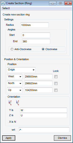
The Create Section (Ring) window is a dual purpose create/modify window, by default the Create Section (Ring) window is displayed. To modify the ring section, refer to Modify Section (Ring).
From the Settings part of the Create Section (Ring) window, the user can specify the radius, start and end angles along with the direction in which the ring section is to be created (Clockwise or Anti-Clockwise).
The start and end angles (points) must now set, from the Angles part of the Create Section (Ring) window. By default the Start angle is 0° and the End angle is 180° with an Anti-clockwise direction. Modify as required.
Use the Position & Orientation part of the Create Section (Ring) window to position and orientate the ring section. However the position and orientation functionality available from the Create Section (Ring) window is identical to that available from the Design Aid functionality, for more information refer to Common Functionality Guide.
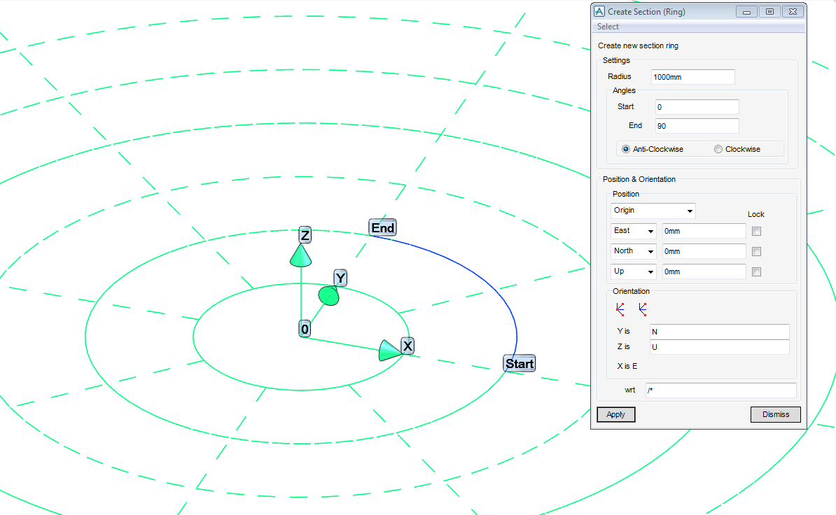
Click Apply to create the ring section.
The settings, position and orientation of a ring section can be modified, first the user must select the ring section to be modified in the model explorer, then click Select. From the drop down list, select CE or Pick (to select the section in the 3D view), the Modify Section (Ring) window is displayed.
Modify the settings, position or orientation of the ring section and then Apply to commit the changes.