Structural Design
User Guide
Sections : Create Sections
On the SECTIONS tab, in the Create group, click Create sections, select Straight from the drop down list to display the Section and Positioning Control window. The user is also prompted to ‘Define section start (Snap) Snap:’.
All the tasks that the user would carry out with the creation of a section are initiated from a central Section window. which acts as a task hub.
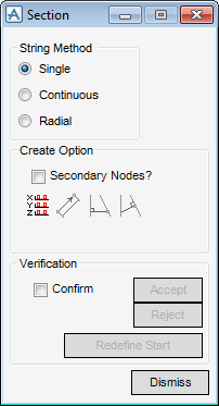
By default the method used to create the new section is Single, MODEL uses the string method to create new sections.
|
•
|
Single - a start and end point.
|
|
•
|
Continuous - a start point with connected sections to the end point.
|
|
•
|
Radial - all sections originate from the same start point.
|
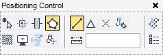
The user can explicitly select a start point in the 3D view as prompted or the user can choose to use another method to choose the section start point with the Positioning Control window.
The Positioning Control window is common throughout MODEL, so therefore is not described here. For more information on the Positioning Control window, refer to the Common Functionality Guide.
Once the user has selected the section start point in the 3D view, the start is labelled and the user is prompted to ‘Define section end (Snap) Snap:’. Select the section end point, the new section is displayed in the 3D view as a dotted line.
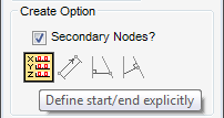
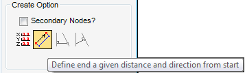
To create secondary nodes automatically as sections are connected, from the Create Option part of the Section window, select the Secondary Nodes? check box, by default the Secondary Nodes? check box is not selected. For more information on secondary nodes, refer to Connectivity.
Select Define Start/End Explicitly, the user must input the exact coordinates for the start of the section or pick a point in the 3D view.
A Define section start window is displayed, the user is prompted to Define section start (Snap) Snap: and the Start position is also displayed in the 3D view.
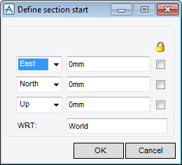
By default, the site origin coordinates populate the Define section start window, East/North/Up (E0, N0, U0).
From the Create Option part of the Section window, select Define End a Given Distance and Direction from Start.
A Define section end window is displayed and the user is prompted to ‘Define section end (Snap) Snap:’.
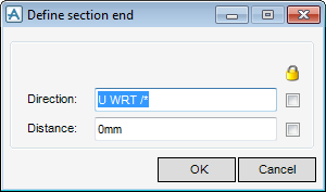
The Define section end window is populated with the defaults: direction U WRT/* and the distance of 0mm.
The minimum length of the section must be 30mm, if the length is under 30mm, an Error window is displayed.
The Verification part of the Section window allows the user to accept, reject or redefine define the start of the section.
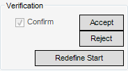
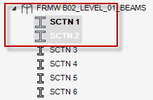
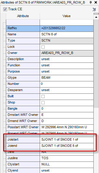
Click Accept to confirm the creation of the Section. The Section is displayed as SCTN 1 in the model explorer.
Click Reject to discard any inputs or click Redefine Start to begin the creation of the section again.
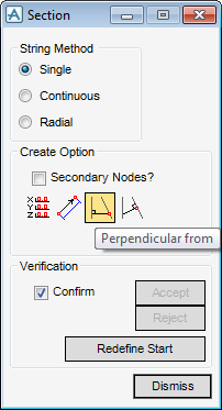
If required the user can create a new section perpendicular from an existing section or straight wall. From the Create Option part of the Section window, select Perpendicular from, the user must select the start position in the 3D view and is prompted to ‘Pick straight Section/Wall to derive perpendicular from’.
Click Accept to confirm the creation of the Section. The Section is displayed as SCTN 1 in the model explorer.
Click Reject to discard any inputs or click Redefine Start to begin the creation of the section again.
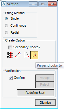
If required the user can create a new section perpendicular to an existing section or straight wall. From the Create Option part of the Section window, select Perpendicular to, the user must select the start position in the 3D view and is prompted to ‘Pick straight Section/Wall to derive perpendicular to end’.
Click Accept to confirm the creation of the Section. The Section is displayed as SCTN 1 in the model explorer.
Click Reject to discard any inputs or click Redefine Start to begin the creation of the section again.
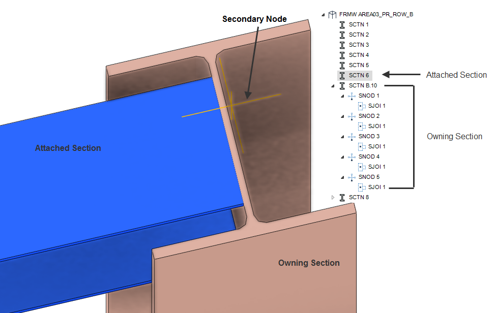
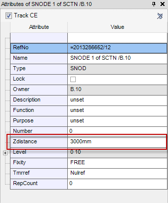
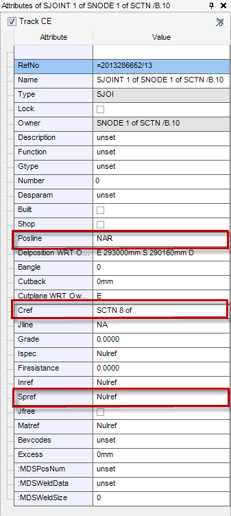
When sections (SCTNs) are connected automatically, secondary nodes are also automatically created (as long as the Secondary Nodes? checkbox is selected in the Section window). The connection between two sections is represented as a secondary joint (SJOI) element in the model explorer.
On the SECTIONS tab, in the Connect group, click Connect, the user is prompted to ‘Identify section to be connected to:’
The user is prompted to ‘Identify section end to be disconnected:’