Structural Design
User Guide
SLH Tools : Components
|
•
|
|
•
|
|
•
|
|
•
|
Panels (only available with panelled handrails selected as the CE).
|
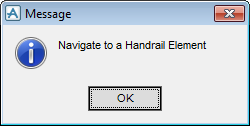
If a particular SLH element cannot be created at the current position in the database hierarchy, the following Message window is displayed.
Dependent upon which handrail components are used, determines which tabs of the Modify Handrail Components window are populated and are available for selection.
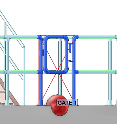
On the Stair Ladders Handrails tab in the Tools group, click Handrail Components to display the Modify Handrails Components window. By default the window is displayed with the Gates tab selected.
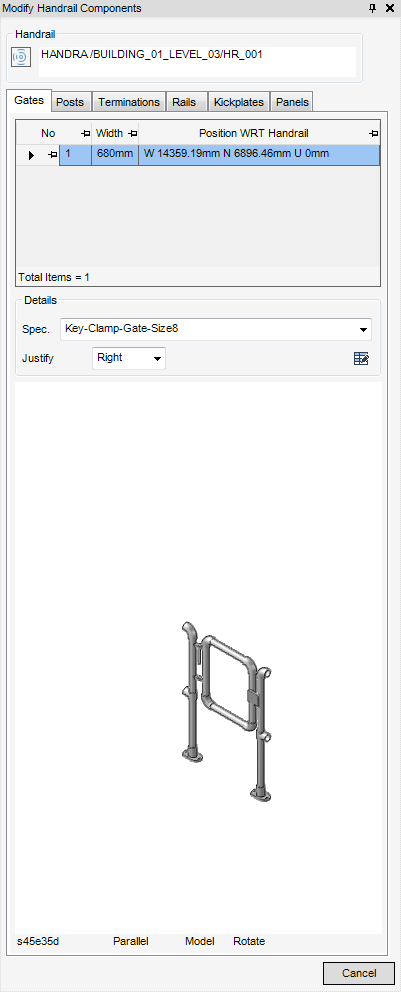
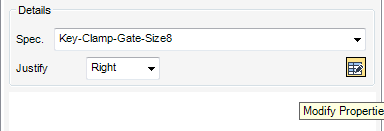
From the Details part of the Modify Handrail Components window, the user can modify the Specification, Justification and Horizontal Offset of the gate.
From the Spec drop down list, select the specification from the displayed list, the gate will be modified to reflect the change in specification. For example - the gate becomes a shallow narrow gate or a chain.
From the Justify drop down list, select a justification from the displayed list.
To modify the horizontal offset of the gate element, click Modify Properties, the Modify Properties window is displayed.
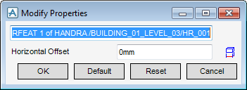
Input the horizontal offset into the Horizontal Offset field or use the 3D graphical view, click Measure Horizontal Offset, the Positioning Control window is displayed, the user is prompted to ‘Measure property dimension start (Distance [0]Snap):. Once the selection has been selected the user is prompted to ‘Measure property dimension end (Distance [0] Snap):’
Click OK to commit to the changes.
Click Default to return the horizontal offset back to the default.
Click Reset to return the horizontal offset back to its original position.
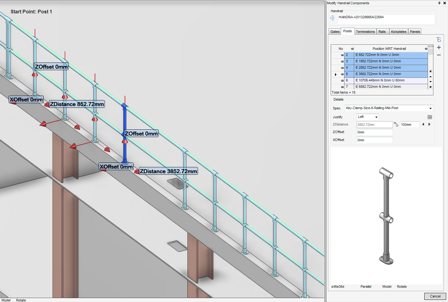
To modify default posts components, from the Modify Handrail Components window, select the Posts tab. The Posts part of the window is populated with a list of all the posts which are used in the handrails, along with other details. By default no single post is selected.
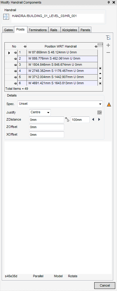
To select and modify a single post, from the Posts part of the Modify Handrail Components window, select the post to be modified. Select the required post from the populated list. The window is populated with the details of the post and a graphical representation of the post.
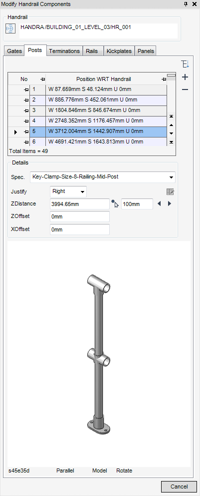
From the Details part of the Modify Handrail Components window, the user can modify the details and attributes of the selected post.
To modify the specification of the selected post, from the Spec drop-down list, select the required specification, the selected post will be amended to reflect the change in the specification. For example, the mid post becomes a corner post.
To modify the justification line of the selected post, from the Justify drop-down list, select Centre, Forward, Back, Right and Left.
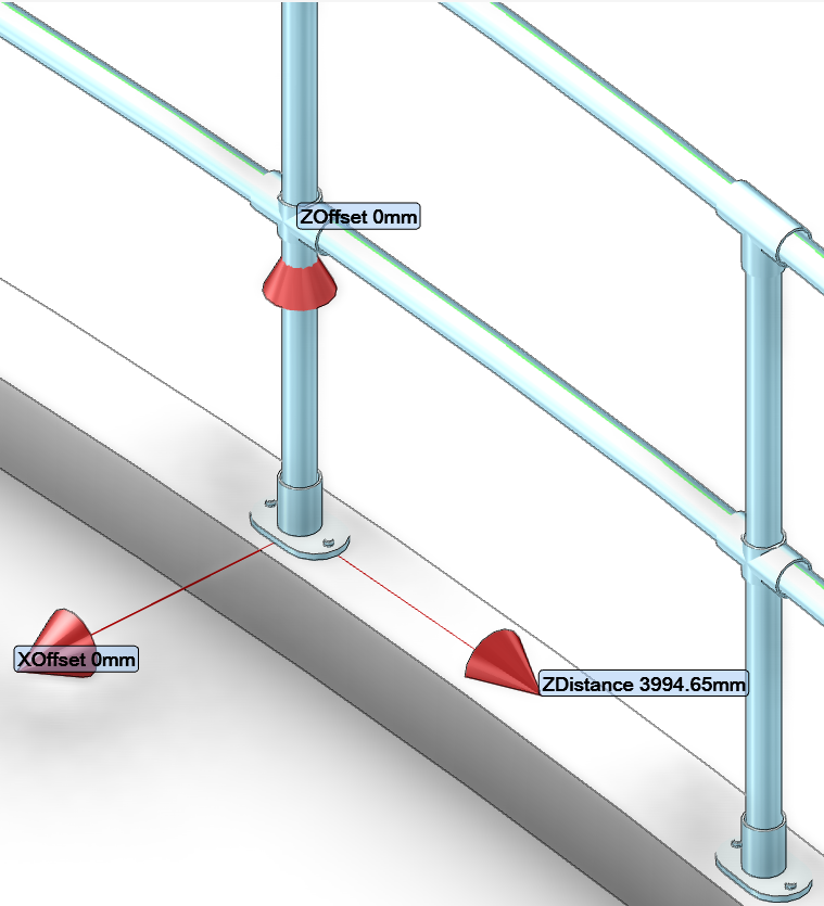
ZDistance - This is the horizontal distance from the start point (Post 1) along the RPATH to the selected handrail.
|
•
|
Input the new distance in the ZDistance field
|
|
•
|
Pick the new position in the 3D graphical view, click Pick New Position, the user is prompted to ‘Pick new position for post (Distance [0]) Snap:’
|
ZOffset - The vertical distance from the route path to the post. The position of the post also depends on the selected justification. The post position for a handrail is taken from the assembly. If required modify the Z Offset.
XOffset - The horizontal distance from the route path to the post in the assembly. The selected posts position for the handrail is taken from the assembly. If required, modify the X Offset.
If required, the user can select and modify multiple posts in the handrail, from the Details part of the Modify Handrail Components window, select multiple posts. The posts are labelled in the 3D graphical view. From the Modify Handrail Components window modify the details and attributes s required.
|
|
The user is prompted to ‘Pick Post to display’ the Positioning window is also displayed. Once selected in the 3D view, the Modify Handrail Components window is populated with details of the selected post. Modify details and attributes as required.
|
|
|
|
The user is ‘Pick the position to insert post (Distance [0]) Snap:’ once selected in the 3D view, the Modify Handrail Components window is populated with details of the selected post. Modify details and attributes as required.
|
|
|
|
To modify default terminations components, from the Modify Handrail Components window, select the Terminations tab. The Terminations part of the window is populated with a list of all the terminations which are used in the handrails, along with other attributes.
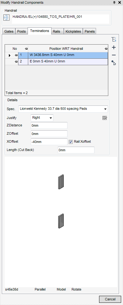
From the Details part of the Modify Handrail Components window, the user can modify the details and attributes of the selected termination
To modify the specification of the selected termination, from the Spec drop-down list, select the required specification. The selected termination will be modified to reflect the change in specification, for example the spacing pads will become an end dee section.
To modify the justification line of the selected termination, from the Justify drop-down list, select Centre, Forward, Back, Right and Left.
ZDistance - This is the horizontal distance from the start point along the RPATH to the selected termination.
ZOffset - The vertical distance from the route path to the termination, the position of the termination also depends on the selected justification. The termination position for a handrail is taken from the assembly.
XOffset - The horizontal distance from the route path to the termination in the assembly, the position of the selected termination for the handrail is taken from the assembly.
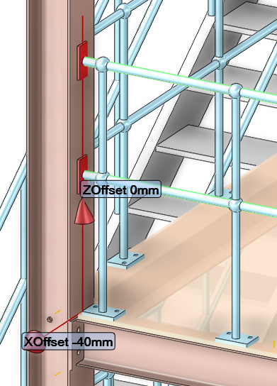
By default the Rail Xoffset checkbox is selected, this means the rail offset aligns with the XOffset.
Length (Cut Back) - the default (0mm) is displayed, in order to add terminations cut the rail, modify as required.
If required, the user can select and modify multiple terminations, from the Details part of the Modify Handrail Components window, select multiple terminations. The terminations are labelled in the 3D graphical view. From the Modify Handrail Components window modify the details and attributes as required.
|
|
The user is prompted to ‘Pick Termination to display’ the Positioning window is also displayed. Once selected in the 3D view, the Modify Handrail Components window is populated with details of the selected termination.
|
|
|
|
The user is ‘Pick the position to insert Termination (Distance [0]) Snap:’ once selected in the 3D view, the Modify Handrail Components window is populated with details of the selected termination.
|
|
|
|
A Confirm window is displayed: ‘Delete the selected Terminations’.
|
|
|
|
Pick the new position in the 3D graphical view, click Pick New Position, the user is prompted to ‘Pick new position for post (Distance [0]) Snap:’
|
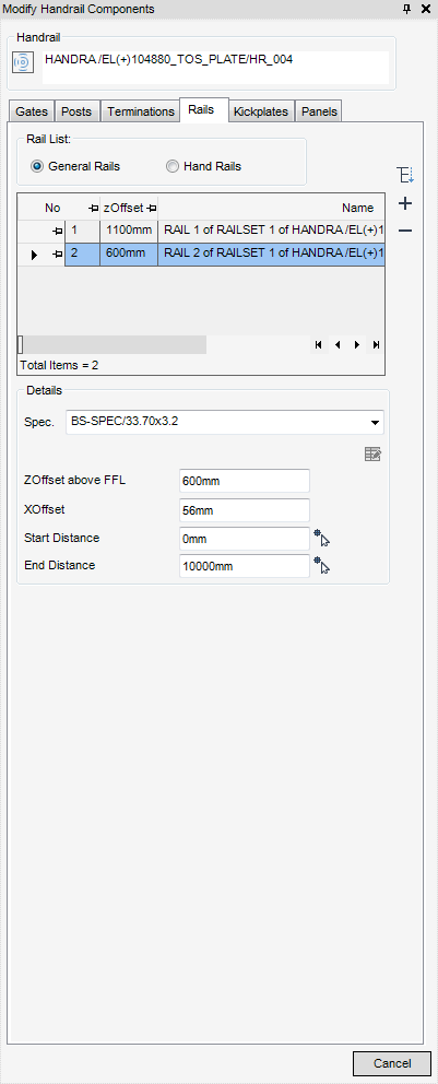
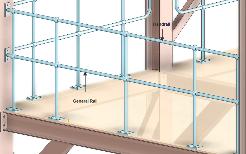
To modify rail components, from the Modify Handrail Components window, select the Rails tab. By default, general rails is selected and these populate the rail list.
|
•
|
From the Rails List of the Modify Components window, click to select the rail to be modified. The details of the selected rail are labelled in the 3D graphical view.
From the Details part of the Modify Handrail Components window, the user can modify the details and attributes of the selected rail.
To modify the specification of the selected rail, from the Spec drop-down list, select the required specification. The selected rail will be modified to reflect the change in specification, for example a circular rail will become a square rail.
To modify the justification line of the selected rail, from the Justify drop-down list, select Centre, Forward, Back, Right and Left.
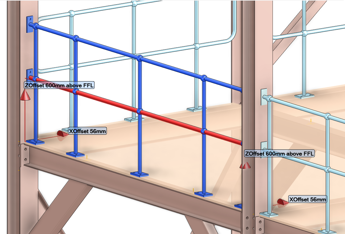
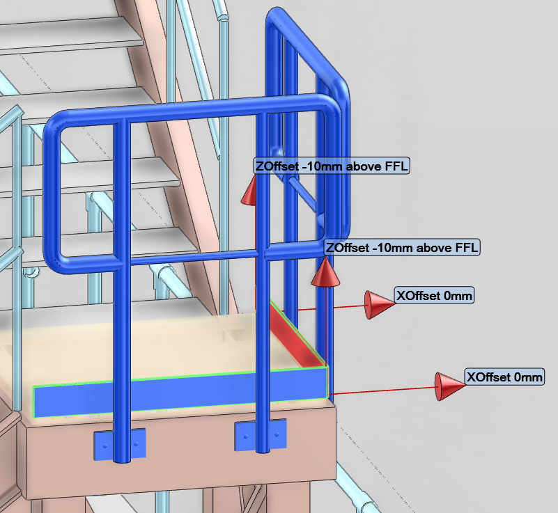
ZOffset above FFL- The vertical distance of the rail from the route path to the rail.
XOffset - The horizontal distance from the route path to the rail in the assembly, the position of the selected rail for the handrail is taken from the assembly.
Start Distance - the default start position is displayed in the Start Distance field, to modify the Start Position, input a new distance into the Start Distance filed, or select Pick New Start Position, the user is prompted to ‘Pick Position (Distance [0]) Snap:’ and the Positioning window is also displayed.
End Distance - the default start position is displayed in the End Distance field, to modify the End Position, input a new distance into the End Distance filed, or select Pick New End Position, the user is prompted to ‘Pick Position (Distance [0]) Snap:’ and the Positioning window is also displayed.
|
|
The user is prompted to ‘Pick Rail to display’ the Positioning window is also displayed. Once selected in the 3D view, the Modify Handrail Components window is populated with details of the selected post.
|
|
|
|
The user is ‘Pick the position to insert rail (Distance [0]) Snap:’ once selected in the 3D view, the Modify Handrail Components window is populated with details of the selected rail.
|
|
|
|
A Confirm window is displayed: ‘Delete the selected posts’.
|
If required, the user can select and modify multiple posts in the handrail, from the Details part of the Modify Handrail Components window, select multiple rails. Only the first and last post are labelled in the 3D graphical view. From the Modify Handrail Components window modify the details as required.
To modify kickplates, from the Modify Handrail Components window, select the Kickplates tab. The Kickplates part of the window is populated with a list of all the kickplates which are used in the handrails, along with other details. By default no single kickplate is selected.
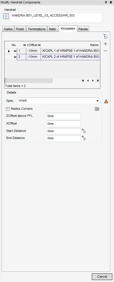
From the Details part of the Modify Handrail Components window, the user can modify the default details and attributes of the selected kickplate.
To modify the specification of the selected kickplate, from the Spec drop-down list, select the required specification. The selected kickplate will be modified to reflect the change in specification.
By default the kickplate has corners with a radius, to have corners which bend, select to un- check the Radius Corners checkbox (bend corners attribute)
ZOffset above FFL- The vertical distance of the kickplate from the route path to the kickplate.
XOffset - The horizontal distance from the route path to the kickplate in the assembly, the position of the selected kickplate for the handrail is taken from the assembly.
Start Distance - the start position is displayed in the Start Distance field, to modify the Start Position, input a new distance into the Start Distance filed, or select Pick New Start Position, the user is prompted to ‘Pick Position (Distance [0]) Snap:’ and the Positioning window is also displayed.
End Distance - the last position is displayed in the End Distance field, to modify the End Position, input a new distance into the End Distance filed, or select Pick New End Position, the user is prompted to ‘Pick Position (Distance [0]) Snap:’ and the Positioning window is also displayed.
|
|
The user is prompted to ‘Pick Kickplates to display’ the Positioning window is also displayed. Once selected in the 3D view, the Modify Handrail Components window is populated with details of the selected post.
|
|
|
|
The user is ‘Pick the position to insert kickplates (Distance [0]) Snap:’ once selected in the 3D view, the Modify Handrail Components window is populated with details of the selected post.
|
|
|
|
A Confirm window is displayed: ‘Delete the selected kickplates’.
|
If required, the user can select and modify multiple kickplates in the handrail, from the Details part of the Modify Handrail Components window, select multiple kickplates. Only the first and last kickplates are labelled in the 3D graphical view. From the Modify Handrail Components window modify the details as required.
To modify panels, from the Modify Handrail Components window, select the Panels tab. The Panels part of the window is populated with a list of all the panel assemblies which are available for selection, along with other details. By default no single panel is selected.
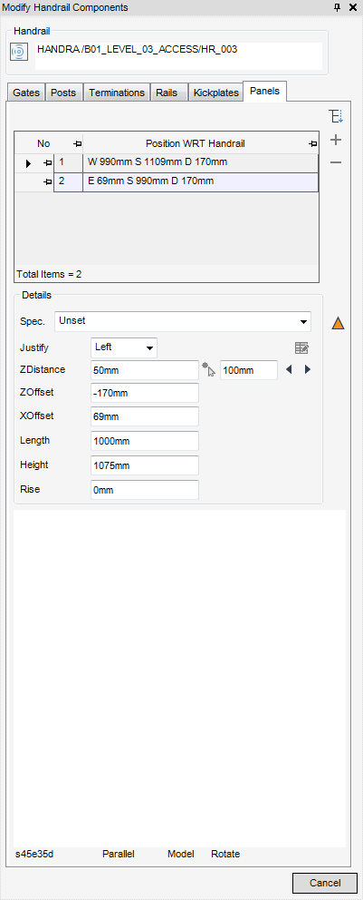
From the Details part of the Modify Handrail Components window, the user can modify the default details of the selected panel.
To modify the specification of the selected panel, from the Spec drop-down list, select the required specification. The selected panel will be modified to reflect the change in specification.
To modify the justification line of the panel, from the Justify drop-down list, select Centre, Forward, Back, Right and Left.
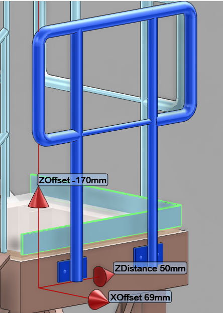
ZDistance - This is the horizontal distance from the start point along the RPATH to the selected panel, to modify:
|
•
|
Input the new distance in the ZDistance field
|
|
•
|
Pick the new position in the 3D view, click Pick New Position, the user is prompted to ‘Pick new position for post (Distance [0]) Snap:’
|
ZOffset - The vertical distance of the panel from the route path.
XOffset - The horizontal distance from the route path to the panel, the position of the selected panel is taken from the assembly.
Length - The length of the panel (default) is displayed, modify as required.
Height - The height of the panel (default) is displayed, modify as required.
Rise - This detail is only available to panel assemblies, it is the vertical distance of the panel from the RPATH when a panel assemblies is used on a slope.
|
|
The user is prompted to ‘Pick panel to display’ the Positioning window is also displayed. Once selected in the 3D view, the Modify Handrail Components window is populated with details of the selected panel.
|
|
|
|
The user is ‘Pick the position to insert panel (Distance [0]) Snap:’ once selected in the 3D view, the Modify Handrail Components window is populated with details of the selected panel.
|
|
|
|
A Confirm window is displayed: ‘Delete the selected panel’.
|
If required, the user can select and modify multiple panels in the handrail, from the Details part of the Modify Handrail Components window, select multiple panels. Only the first and last panels are labelled in the 3D graphical view. From the Modify Handrail Components window modify the details as required.