Structural Design
User Guide
Handrails : Create Handrail
On the STAIRS LADDERS HANDRAILS tab, in the Create group, click Handrail, the Create Handrail window is displayed.
Layout is a basic representation of the intended handrail. The database only contains the handrail and its intended route plus any openings for gates, that is the handrail does not own any detailed components. For more information, refer to Layout Handrails Hierarchy.
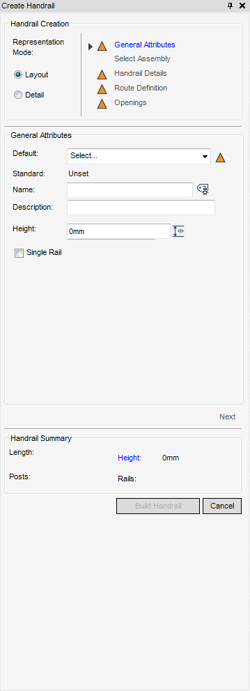
From the General Attributes part of the Create Handrail window, select a default specification from the drop- down list of available specifications, if there are no default specifications, the user must contact the System Administrator.
If required, type in a description for the handrail in the Description box.
The Height field is automatically populated with the default height of the handrail, once the default specification has been selected.
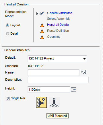
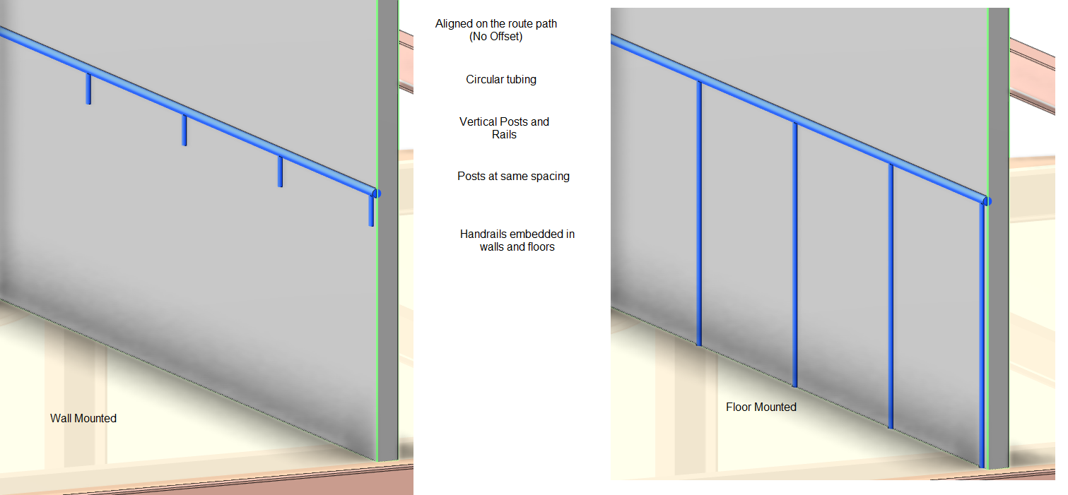
Use the Single Rail check box to specify if the single handrail is to be wall mounted or floor mounted. Select the Single Rail check box, then Wall Mounted or Floor Mounted.
|
Note:
|
If the user selects the Single Rail check box, no are kick plates are available for selection. For more information, refer to Kick Plates.
|
The Handrail Details part of the Create Handrail window, is populated with the standard defaults for the handrail.
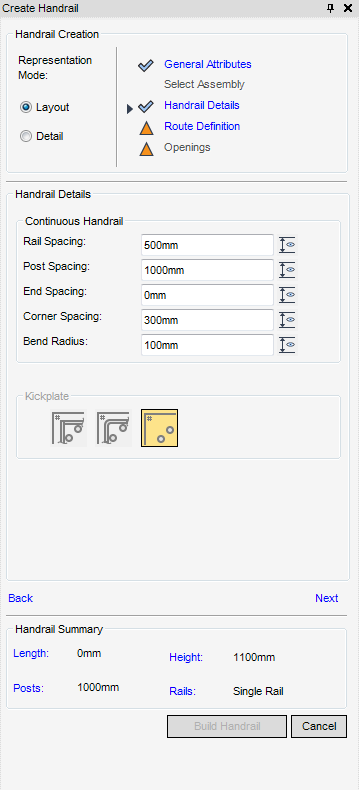
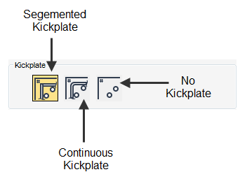
Use the Kickplate part of the Create Handrails window to specify what type of kickplate or no kickplate is required in the layout handrail.
Select Back to discard any inputs and return to the General Attributes part of the Create Handrail window.
|
•
|
Create Route Points - enables the user to select points in the 3D graphical view. The minimum route points required is two.
|
|
•
|
Copy Route Path - enables the user to trace a path from an existing profile or boundary in the 3D graphical view. (The availability of this functionality can be restricted by the system administrator).
|
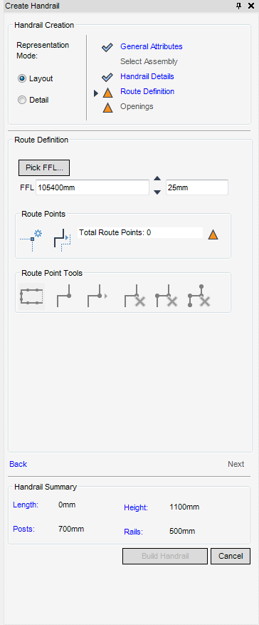
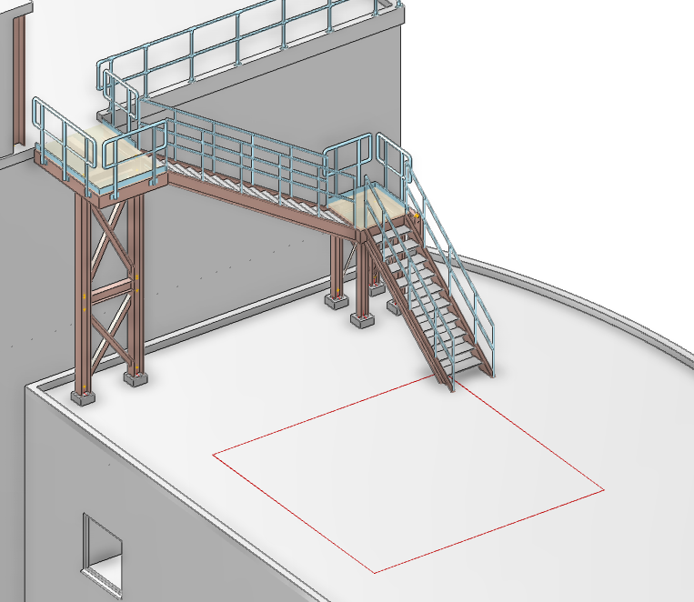
Irrelevant of the method used, when defining the route, the Finished Floor Level (FFL) and at least two route points needs to be defined. From the Route Definition part of the Create Handrail window, select Pick FFL. The user is prompted to ‘Pick Finished Floor Level’. It is usual to pick a horizontal surface, where the FFL field in the Route Definition part of the Create Handrail window is automatically populated.
Use the Route Points part of the Route Definition window, to create the route points for the handrail route.
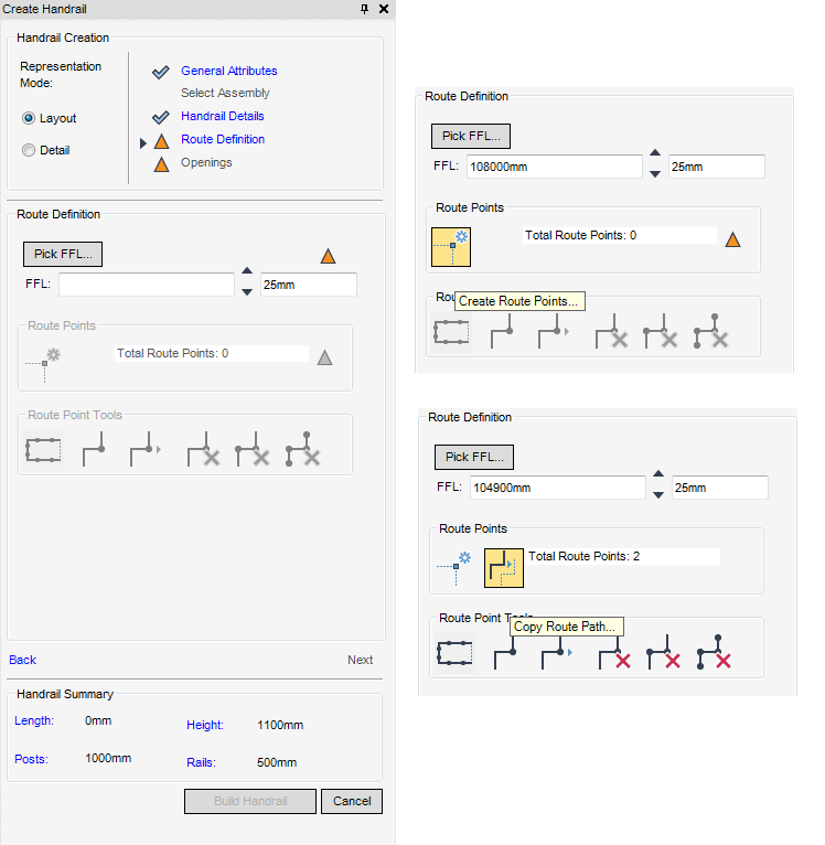
Select Create Route Points, the user is prompted to ‘Pick Position of first route point (Distance [0]) WP Snap:’ in the 3D view. Once the point has been selected the user is prompted to ‘Pick Position of new route point (Distance [0]) WP Snap:’ in the 3D view and the user now has access to the Route Point Tools functionality. For more information on route point tools, refer to Route Point Tools.
The Copy Route Path functionality allows the user to trace existing profiles or boundaries to use as route path. For example: extrusions, panels, floors, GENSECs, walls and stair flights.
From the Route Definition of the Create Handrail window, select the FFL, then select Copy Route Path.
The user is prompted to ‘Pick element to copy route point from:’ in the 3D graphical view.
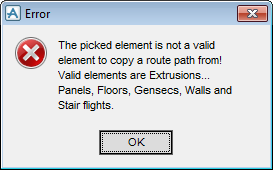
If the user picks an unsuitable element in the 3D graphical view, the following Error window is displayed.
If the user picks a valid element in the 3D graphical view, the following Confirm window is displayed:
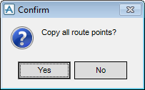
Click Yes to copy the route path of the existing profile or boundary.
Click No to discard any inputs.
Use the Openings part of the Create Handrail window to create an opening for the layout handrail. For more information on openings, refer to Openings.
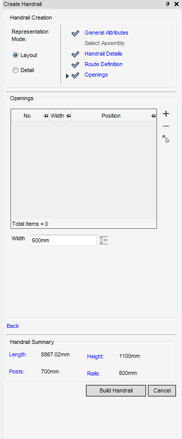
Click Build Handrail to create the handrail in Layout.