Structural Design
User Guide
Rung Ladder : Detail Mode
The Detail Mode is intended for use by structural designers to fully define the rung ladder, by selecting a default, an assembly and the specification references of the ladder components.
An rung ladder element created in Layout may be modified to a detailed representation without deleting and re-creating the element.
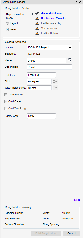
The functionality available for the General Attributes of the Rung ladder in the Detail Mode is identical to that described in the Layout mode, for more information refer to General Attributes.
The functionality available for the Position and Elevation of the Rung ladder in the Detail Mode is identical to that described in the Layout mode, for more information refer to Position and Elevation.
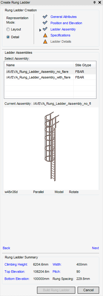
The Ladder Assembly part of the Create Rung Ladder window is automatically populated with all of the available assemblies for selection that contain the selected exit type. A 3D graphical representation of the assembly is also displayed.
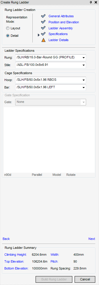
The Specifications part of the Create Rung Ladder window displays all the available specifications for the rung ladder from the defaults.
Dependent upon the choices made by the user on previous parts of the Create Rung Ladder determines which specifications are available for selection.
From the Gate Specification part of the Create Rung Ladder window, the gate specifications available for selection from the drop-down list are determined by the default specification. The default is None.
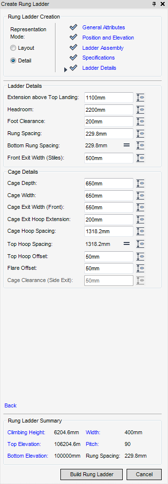
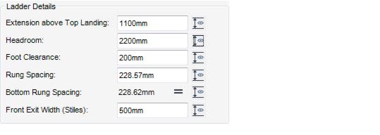
The Ladder Details part of the Create Rung Ladder window is populated with the selected and calculated values, most of these values are constrained by the specifications. Any of the ladder dimensions can be modified as long as the dimensions remain within the maximum and minimum tolerances of the associated standard.
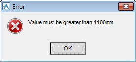
If the user enters a dimension which is not within the maximum and minimum tolerances of the associated standard, an appropriate Error window is displayed.
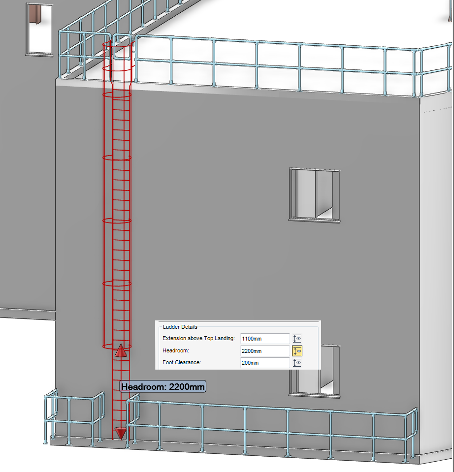
Any of the dimensions displayed in the Create Rung Ladder window can be labelled in the 3D view. To label the dimension, click dimension alongside the dimension field.
The Ladder Details part of the Create Rung Ladder window is populated with the selected and calculated values, most of these values are constrained by the specifications.
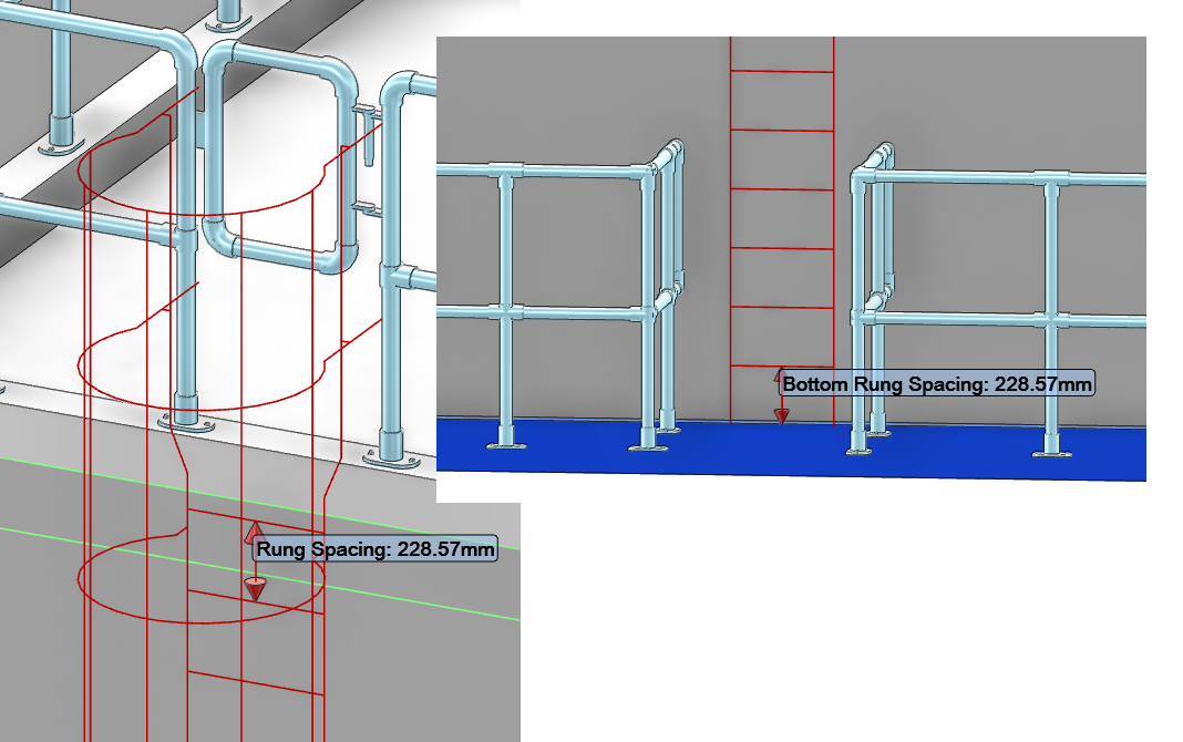
If required the user can modify the rung spacing and as a result the bottom rung spacing. From the Ladder Details part of the Create Rung Ladder window, input the new rung spacing into the Rung Spacing field, then press enter.
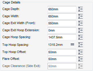
The Cage Details part of the Create Rung Ladder window is only displayed if the Omit Cage or Omit Top Rung check box on the General Attributes part of the Create Rung Ladder window is selected.
The Cage Details part of the Create Rung Ladder window is populated with the selected and calculated values, most of these values are constrained by the specifications.
Flare Offset - only available if an assembly with a cage flare has been selected.
Cage Clearance (Side Exit) - only available for side ladders.
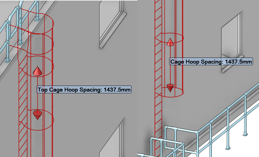
If required the user can modify the rung spacing and as a result the bottom rung spacing. From the Ladder Details part of the Create Rung Ladder window, input the new rung spacing into the Cage Hoop Spacing field, then press enter.
Select Build Rung Ladder to create the rung ladder element, in the database and close the Create Rung Ladder window.
The Rung Ladder Summary part of the Create Rung Ladder window, is populated with the main attributes of the rung ladder. If required, before the creation of the rung ladder element the user can select the attribute by name and modify it from the displayed part of the Create Rung Ladder window.

