Structural Design
User Guide
Rung Ladder : Layout Mode
By default the Representation mode is Layout and General Attributes part of the Create Rung Ladder window are displayed.
From the General Attributes part of the Create Rung Ladder window, select a default standard from the drop-down list of available standards, if there are no default standards, refer to the SLH Administrator, the default is Select.
If created by the SLH system administrator, the standard and default width are automatically displayed in the General Attributes part of the Create Rung Ladder window, once the default has been selected.
The default Standard, Pitch and Width inside stiles values are automatically populated in the General Attributes part of the Create Rung Ladder window.
In the Name: field, type the name for the new rung ladder, or select Autoname Rung Ladder. The default is Unset.
If required, type in a description for the rung ladder in the Description field. The default is Unset.
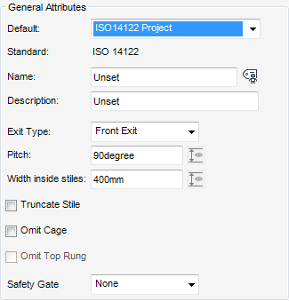
The Exit Type: defines a front, left or right side exit for the rung ladder, from the Exit Type drop-down list, select one of the available exit types.
The Pitch specifies the incline of the rung ladder, dependent upon the default specification selected determines the default pitch. If required, modify the Pitch for the rung ladder within the allowable range from the standard.
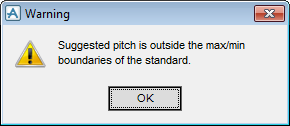
If the user inputs a pitch which is outside the allowable range from the standard, an Error message is displayed.
The Width inside stiles is the width of the horizontal rung within the two vertical stiles, dependent upon the default specification selected determines the default width. The maximum and minimum tolerances can be displayed, if required, modify the Width inside stiles for the rung ladder within the allowable range from the standard.
If the user inputs a width which is outside the allowable range from the standard, an Error message is displayed.
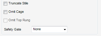
If required, select the Truncate Stile check box to shorten the bottom stiles of the ladder.
If required, for design purposes, select the Omit Cage check box to omit the cage from the 3D view, if allowed by the defaults.
if required, for top access, select the Omit Top Rung check box to omit the top rung from the 3D view, if allowed by the defaults.
The Safety Gate functionality is only available when a cage is included in the rung ladder design and if a safety gate is allowed by the default. From the drop-down list, select Right-side Hinge or Left-side Hinge, the default is None.
The Position and Elevation part of the Create Rung Ladder window contains all the tools for the user to select the position and elevation of the rung ladder and if required modify the position or elevation.
By default, the Evaluation pane of the Create Rung Ladder window, is populated with the statement ‘Top Exit Edge and Bottom Elevation not specified’.
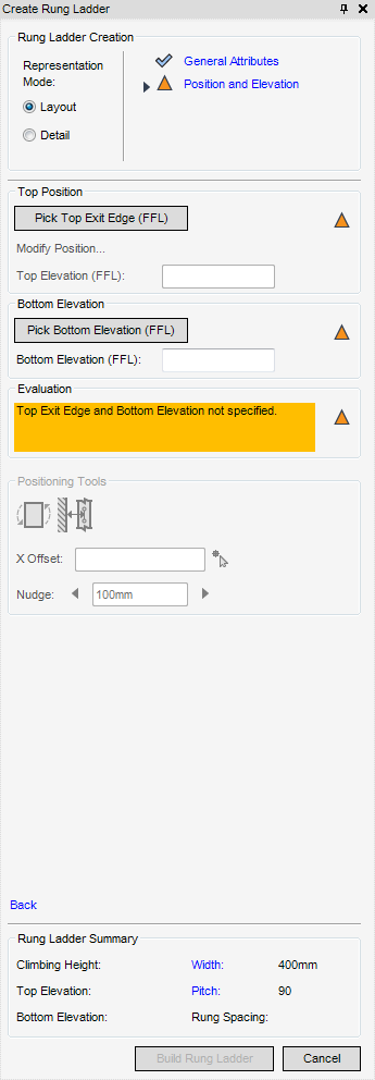
The top position of the rung ladder element defines the position and direction of the rung ladder. The position of the rung ladder is the centre point of the top face of the top rung (level with the FFL), use the Top Position part of the Create Rung Ladder to select the position of the top of the rung ladder.
From the Top Position part of the Create Rung Ladder window, click SLH Rung Ladder - Pick Top Exit Edge: the user is prompted to SLH Rung Ladder - Pick Top Exit Edge:
Once the user has selected the Top Edge is labelled in the 3D view and the Top Elevation (FFL) field of is populated with the elevation.
The Elevation part of the Create Rung Ladder window prompts the user ‘Bottom Elevation not specified’. Click Pick Bottom Elevation (FFL), the user is prompted to ‘SLH Rung Ladder - TO Elevation (Distance[0]): Snap’.
Once the user has selected the Bottom Elevation in the 3D view, and the Bottom Elevation field is populated with the elevation.
If required the user can modify the position of the top exit edge, click Modify Position the Rung Ladder Position window is displayed.
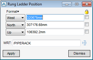
Click Apply to modify the position of the rung ladder
Once both the Top Exit Edge and Bottom Elevation have been selected, the Evaluation pane is populated with the statement ‘Climbing height complies with the standards’.
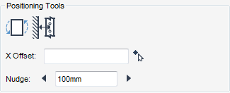
Use the Positioning Tools part of the Create Rung Ladder window to flip the direction of the ladder or reposition the ladder from a dominant foot clearance edge. The ladder can also be moved in it’s X or Y direction.
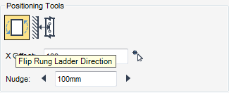
If required, the user can flip the ladder direction 180 degrees across the picked exit edge, select Flip Rung Ladder Direction.
From the Positioning Tools part of the Create Rung Ladder window, click Pick Foot Clearance Edge. The user is prompted to SHL Rung Ladder - Pick Foot Clearance Edge.
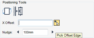
Use the X Offset to position the rung ladder a pre-set distance from an object along the top exit edge.
Type an offset into the X Offset field (the default units are mm), then click Pick Offset Edge, the user is prompted to SLH Rung Ladder Offset Position (Snap) Snap: in the 3D view. Once the user has picked the offset, the rung ladder is offset with respect to the centreline of itself.
Click Build Rung Ladder to create a new rung ladder element and close the Create Rung Ladder window.
Click Cancel to discard any changes and return to the General Attributes part of the Create Rung Ladder window.