Structural Design
User Guide
Stair Flight : Detail Mode
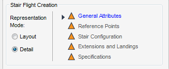
In the Detail mode, extra functionality is available to the user. From the STAIRS LADDERS HANDRAILS tab, in the Create group, click Stair Flight to display the Create Stair Flight window. By default the Layout is selected, select Detail.
The General Attributes part of the Create Stair Flight window, the functionality available to the user is identical to that in Layout Mode. For more information, refer to General Attributes.
The Reference Points part of the Create Stair Flight window, with Detail selected has the mostly the same functionality as that available from Layout with the exception of the connections in the Pick Support Element functionality. This functionality is also available to the ‘TO’ Reference Point.
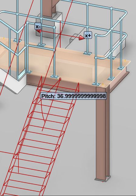
Use to select a support element (GENSEC or SCTN) in the 3D view, selecting a support element offsets the stringer so that the stringer top of steel is flush with the top of steel of the support element. It also establishes a connection between the stringers and the support element and for this reason, only GENSEC’s and SCTNs are valid for picking. The support element must be horizontal, Click Pick Support Element, the user is prompted to ‘SLH - Stair Flight - Pick FROM Support Element’.
Select the Connect check box to establish the connections.
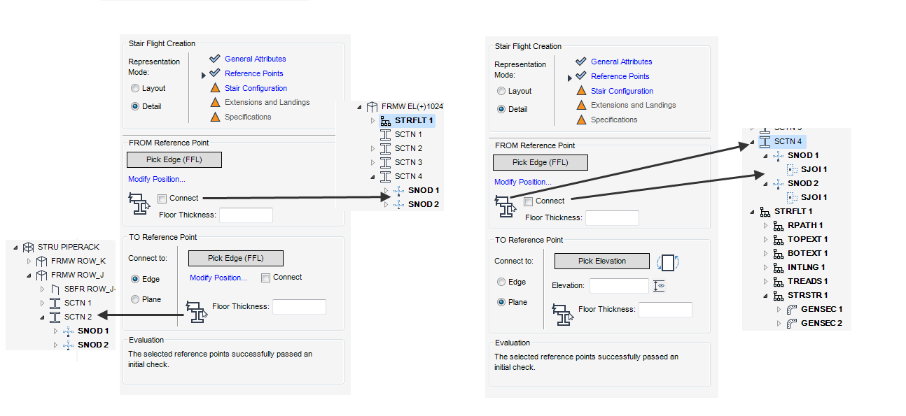
In the structural hierarchy, Secondary Node (SNOD) and SJOI elements are created, for more information on these elements refer to Secondary Nodes and Secondary Joint.
The functionality available to the user is identical to that in Layout. For more information, refer to Reference Points.
The Stair Configuration part of the Create Stair Flight window, with Detail selected has the mostly the same functionality as that available from Layout with the exception of the Pitch Validation functionality.
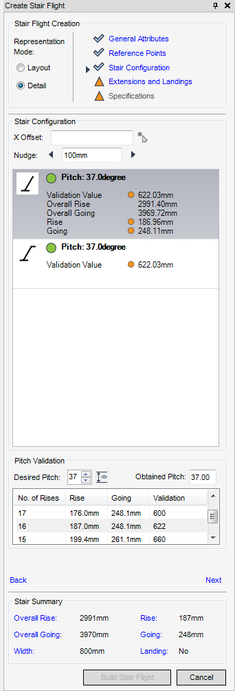
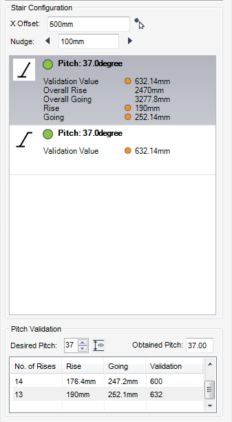
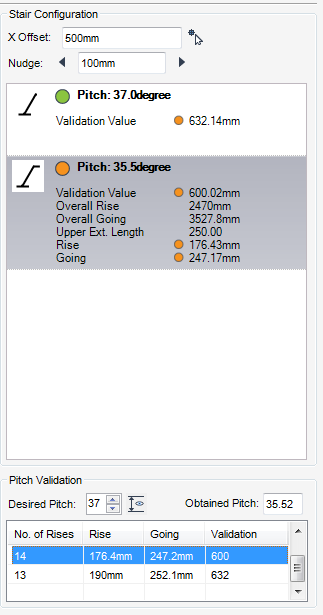
From the Stair Configuration part of the Create Stair Flight window, the user can use the X Offset and Nudge functionality to move the stair flight element along the upper reference edge.
If required, the user can offset the stair flight with respect to the centreline itself. For more information, refer to X Offset
Used for positioning the stair flight along the upper reference edge, for more information refer to Nudge
The Pitch Validation part of the Stair Configuration window, enables the user to modify the desired pitch and as a result the number of rises. It also provides the obtained pitch and an overview of the rise, going and validation for each rises.
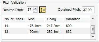
The Obtained Pitch field of the Pitch Validation part of the Stair Configuration window, displays the pitch that is obtained for the currently selected configuration.
The Extension and Landings part of the Create Stair window, with the Detail mode selected has the mostly the same functionality as that available from the Layout mode with the exception of the Stringer functionality.
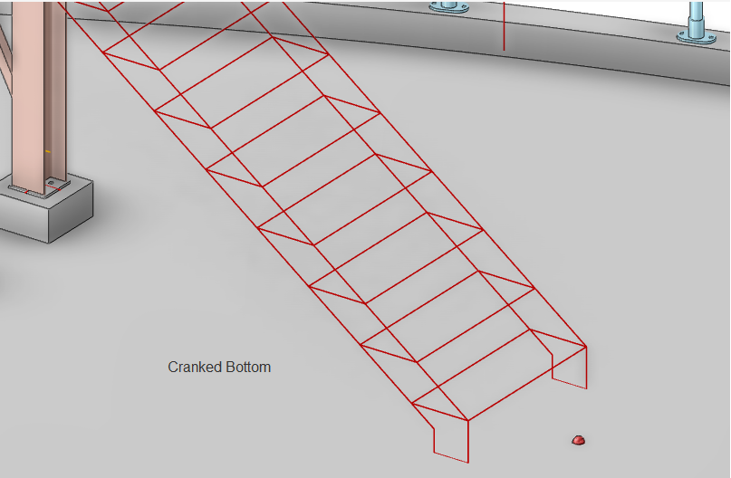
Only available in Detail, the user can if required crank the bottom of the stringers or extend them through the floor.
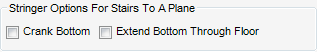
From the Stringer Options part of the Extension and Landings window, select the Crank Bottom of Stringers (only for stairs to a plane) check box. The stringers of the stair are cranked at the selected plane and displayed as such in the 3D view.
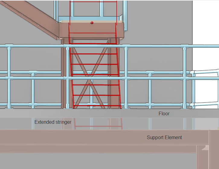
From the Stringer Options part of the Extension and Landings window, select the Extend Bottom Through Floor check box. The stringers of the stair are cranked at the selected plane and displayed as such in the 3D view.
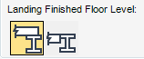
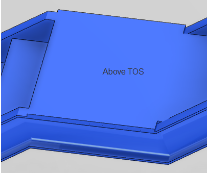
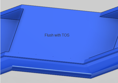
The user can specify if the landing (represented as a PANE element) is on top of or flush with TOS of the stringers, from the Finished Floor Level part of the Extensions and Landings window, select Above TOS or Flush with TOS.
|
|
 |
|
|
|
 |
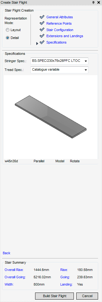
The Specifications part of the Create Stair window, with Detail selected is populated with the specifications available for selection for the stringers and treads of the stair flight element.
Unlike in the Layout mode, adding handrails to a stair flight element in the detail mode is a separate task using the Create Handrails functionality. For more information, refer to Handrails.
The Stair Summary part of the Create Stair Flight window, is populated with the main attributes of the stair flight. If required, before the creation of the stair flight element the user can select the attribute by name and modify it from the automatically appropriately displayed part of the Create Stair Flight window.