Structural Design
User Guide
Stair Flight : Create Stair Flight
On the STAIRS LADDERS HANDRAILS tab, in the Create group, click Stair Flight to display the Create Stair window.
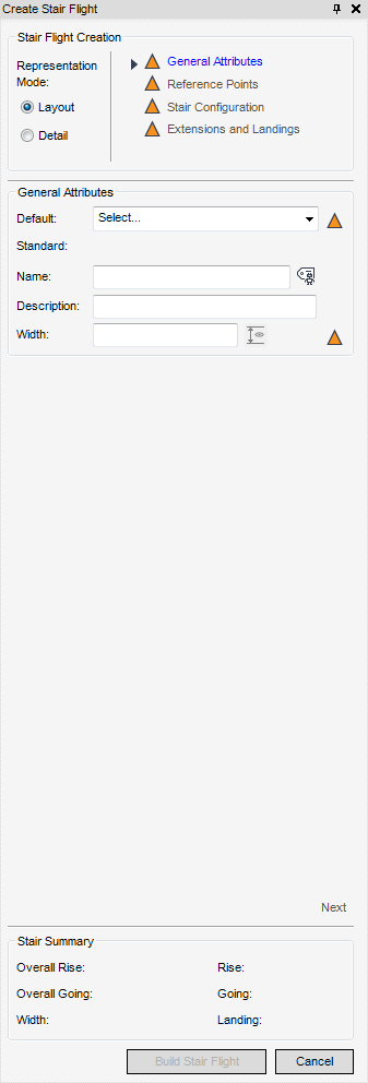
All of the tasks that the user would carry out with the creation of a STRFLT are initiated from a central Create Stair Flight window which acts a task hub. The ‘General Attributes’ window is always the initial window, regardless of the selected SLH element or representation mode, further windows are presented (progressive disclosure) prompting for user input.
|
|
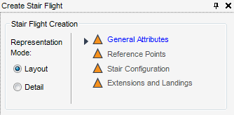
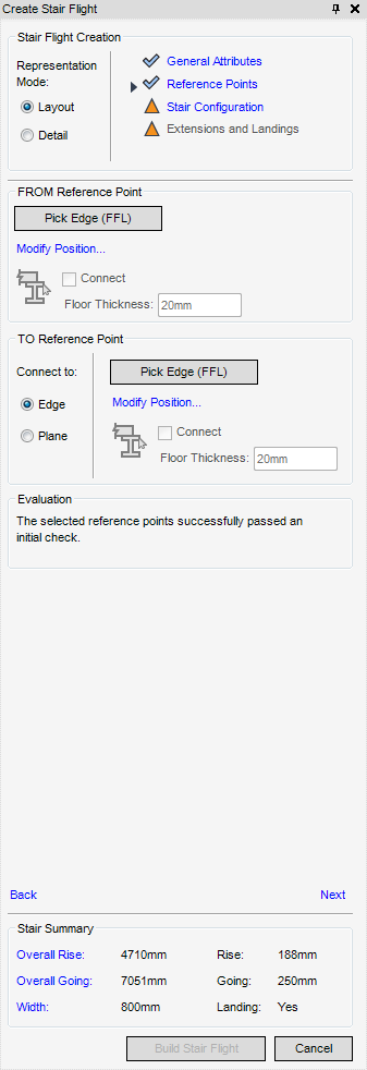
By default the Representation Mode is Layout and General Attributes part of the Create Stair Flight window is displayed.
From the General Attributes part of the Create Stair Flight window, select a default standard from the drop-down list of available defaults, if there are no defaults, refer to the SLH Administrator, the default is Select.
The selected standard to which the default relates and the default width are automatically displayed in the General Attributes part of the Create Stair Flight window.
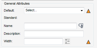
In the Name: field, type the name for the new STRFLT element, or select Autoname Stair Flight. The default is Unset.
The Width field specifies the width of the STRFLT element, it is automatically populated with the default of the selected standard (if set up by the SLH administrator). If required the user can amend the width of the STRFLT element within the minimum and maximum defaults.
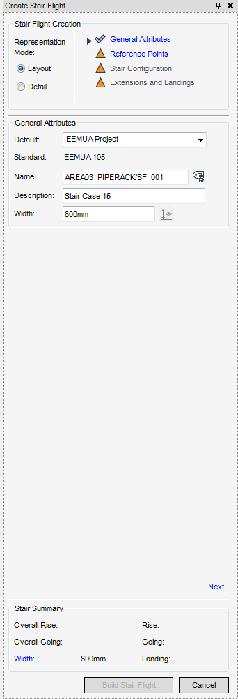
The Stair Summary part of the Create Stair Flight window is populated with the Width dimension of the STRFLT element.
To create a new STRFLT element, the user must select a start (FROM Reference Point) and end (TO Reference Point) for the STRFLT element, from the Reference Points part of the Create Stair window. By default no reference points are selected.
|
•
|
|
•
|
|
Note:
|
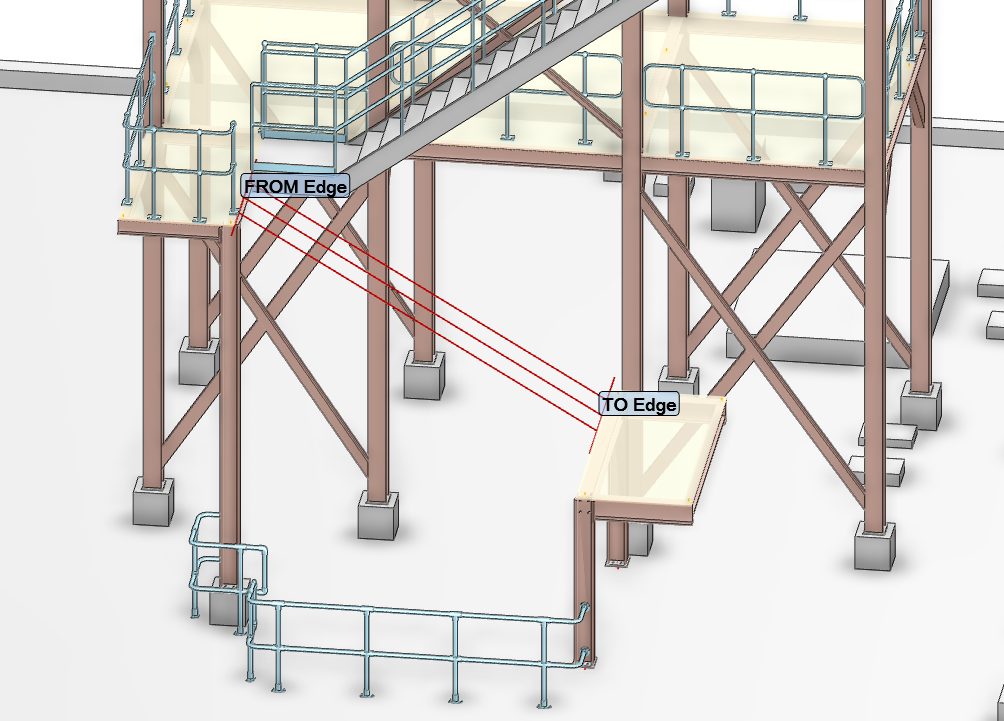
If the user selects the FROM Reference Point first, from the FROM Reference Point part of the Reference Points window, select Pick Edge (FFL). The user is prompted to ‘SLH Flight - Pick FROM Edge’. Once the edge has been selected it is labelled as FROM Edge in the 3D view.
From the TO Reference Point part of the Create Stair window, select Pick Edge (FFL), the user is prompted to ‘SLH Flight - Pick FROM Edge’. Once the edge has been selected it is labelled as TO Edge in the 3D view.
The Evaluation part of the Create Stair window is populated with feedback on the reference points. When the selected reference points are acceptable, the following message is displayed: ‘The selected reference points successfully passed an initial check.’
If required, the user can modify the reference points explicitly, the functionality to modify either edge position is identical for the purposes of this guide, only the FROM Reference Point is described.
The modification process of TO and FROM Reference Points is identical, therefore for the purposes of this user guide, only the FROM Reference Point position modification is described.
To modify the FROM Reference Point position, from the FROM Reference Point part of the Create Stair window, select Modify Position, the FROM Position window is displayed.
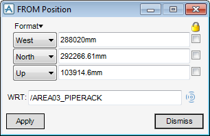
Modify the position of the FROM Reference Point position as required, click Apply to modify the position and close the FROM Position window, or click Dismiss to discard any changes and close the window.
|
Note:
|
Modifying the FROM or TO Position does not reset the stair direction.
|
To modify the offset or to nudge the reference points, refer to X Offset and Nudge for more information.
Used when creating an edge to plane stair flight, this means that the STRFLT element is anchored at the upper reference point and the lower reference point is located freely on the chosen elevation. The user must select the upper reference point first, the functionality is identical to that when creating an edge to edge STRFLT element (the FROM or TO Reference Point) for more information, refer to Edge to Edge.
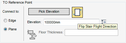
From the To Reference Point part of the Create Stair Flight window, select Pick Elevation, the user is prompted to ‘SLH Stair Flight - Pick Face or Edge’ in the 3D view.
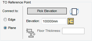
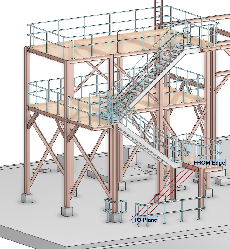
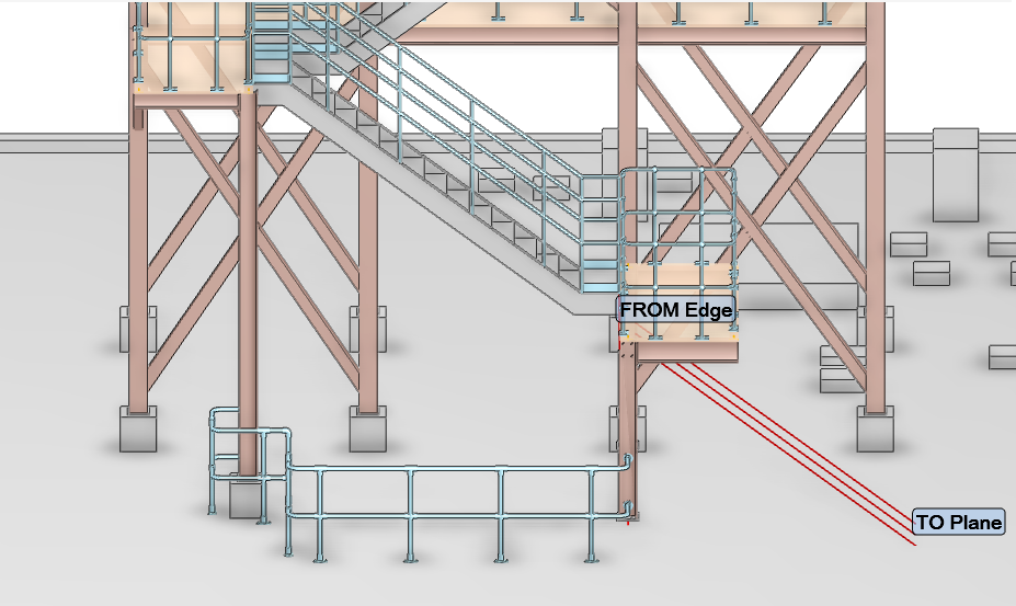
Once the elevation of the lower reference point has been selected, it is labelled as TO Plane in the 3D view and the Elevation field is populated.
If required the user can alter the direction of the STRFLT element, from the TO Reference Point part of the Create Stair Flight window, click Flip Stair Flight Direction.
From the TO Reference Point part of the Create Stair Flight window, click ‘Pick Support Element’. The user is prompted to ‘SLH Stair Flight - Pick FROM Support Element’.
Once the Stair Configuration part of the Create Stair Flight window is displayed, it is automatically populated with all the allowable configurations allowed in the defaults.
Dependent upon which defaults are set by the SLH System Administrator determines which configurations are displayed in the Stair Configuration part of the Create Stair Flight window.
|
|
|
|
|
|
|
|
|
|
|
|
|
|
|
|
|
|
|
|
|
|
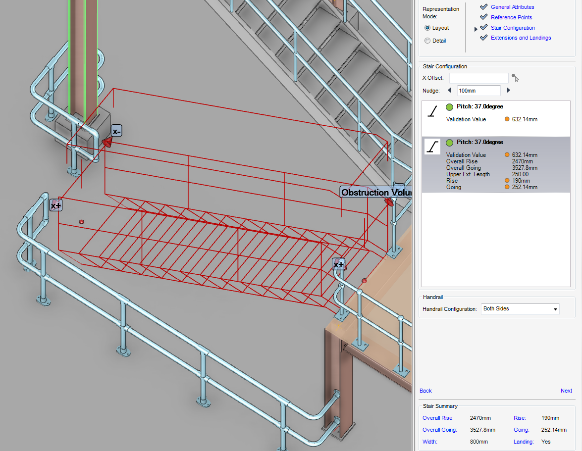
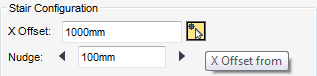
From the Stair Configuration part of the Create Stair Flight window, input the offset distance into the X Offset field then select X Offset from.
The Positioning Control window is displayed, the functionality allows the user to pick positions in event-driven graphics mode. For more information on the Positioning Control window, refer to Positioning Control.
Used for positioning the stair flight along the upper reference edge. Input the nudge increment into the Nudge field (default 100mm), click the arrows to nudge the strair flight along the X axis in the 3D view.
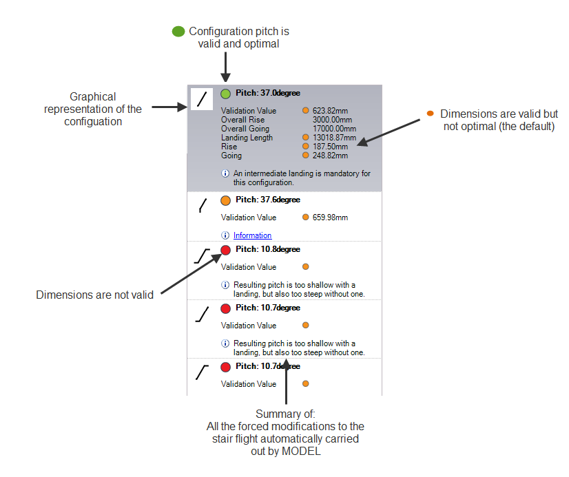
All of the configurations available for selection are displayed in the Stair Configuration part of the Create Stair window. By default the configuration closest to the defaults is highlighted.
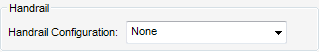
The user can now add handrails to the stair flight, from the Handrail part of the Create Stair window, select the from the Handrail Configuration drop down list of available handrails.
The Extension and Landings part of the Create Stair Flight window is populated with data for the new STRFLT element.
Some of the fields in the Create Stair Flight window are populated with the defaults set by the SLH System Administrator and others are populated with results of calculations made by the SLH application using the defaults file.
|
Note:
|

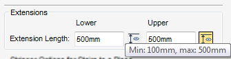
The Extensions pane of the Extensions and Landings part of the Create Stair window is populated with the lower and upper extension lengths (which are within the minimum and maximum default values) for the new STRFLT element.
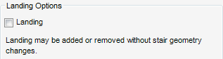
Dependent upon the selected configurations, the Landing part of the Extensions and Landings window can be used to configure, add or remove the intermediate landing to user/company standards and/or requirements.
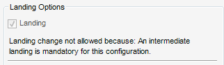
A landing may be mandatory for some configurations and there may not be room for one in others. Therefore the Landing check box is greyed out, and a reason is displayed.
|
Note:
|
The selected configuration must have a intermediate landing as a result the Landing check box is selected.
|
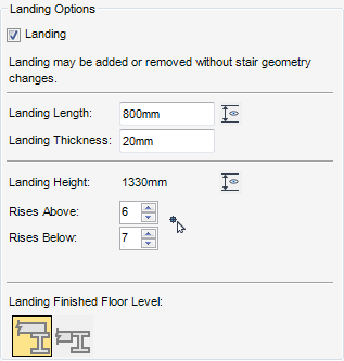
To add a landing, click to select the Landing check box, the SLH application adds a landing to the stair flight.
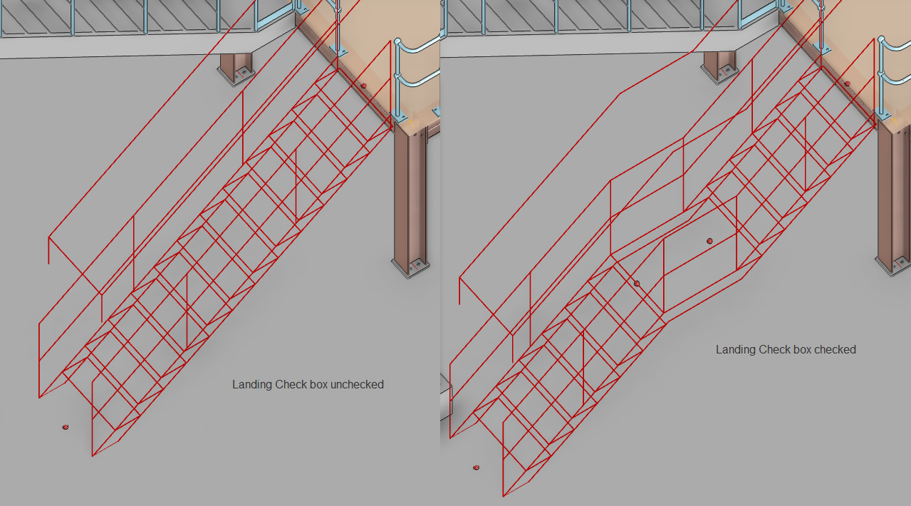
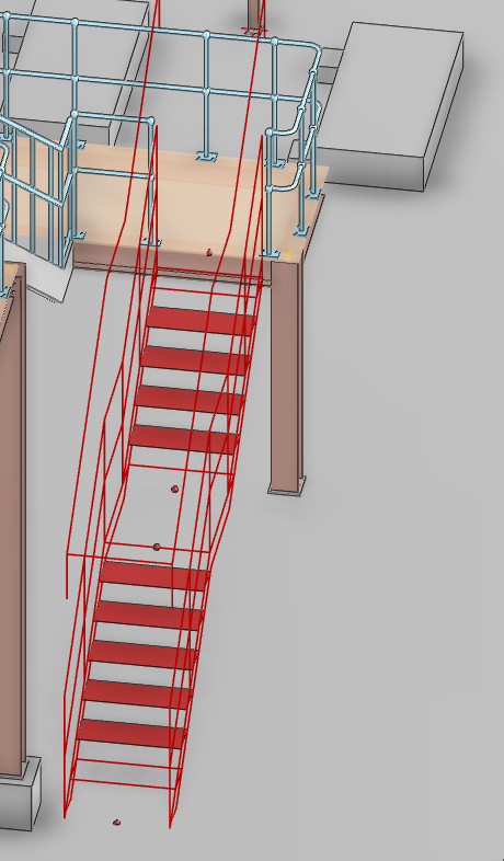
By default, the landings are positioned as close to the middle of the new stair flight element (Landing Height), the Landing Length and Thickness specified in the defaults file are displayed in the Landing Options field part of the Create Stair Flight window.
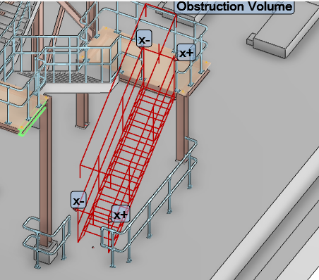
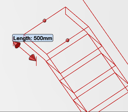
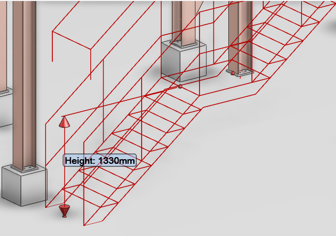
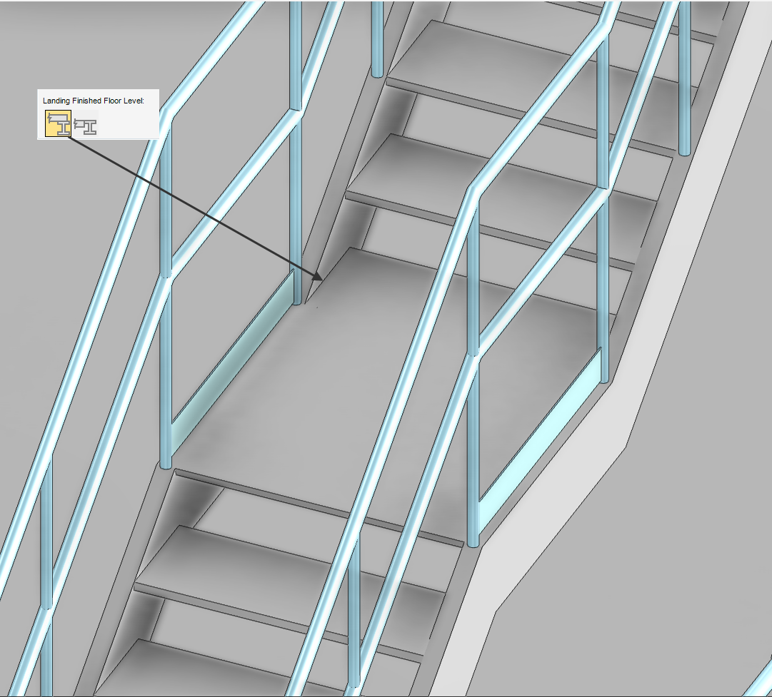
Use the dimension label from the Landing Options part of the Create Stair Flight window, to display the length and/or height of the landing in the 3D view.
|
•
|
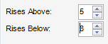
In the Rises Above or Rises Below boxes, select the number of rises above and below the landing. If the user changes the number of rises above the landing the number of rises below the intermediate landing automatically adjusts within the height constraint and vice versa.
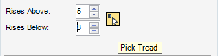
The intermediate landing automatically moves up or down depending upon user selection in the 3D graphical view, the Rises Above and Rises Below boxes are also automatically updated to reflect the amendment.
To create the new stair flight element, click Build Stair Flight.