Structural Design
User Guide
Plates Settings
: How Panels are Represented
How Panels are Represented
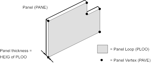
A Panel (PANE) element can be used to represent any sheet material used to clad a structural model. With a similar principle to that for representing a Section (which is an extruded 2D catalogue Profile), a Panel is represented by extruding a user-defined 2D shape. Its geometry is defined by two types of data:
•
The panel’s planar area is defined by a Panel Loop (PLOO) element, which is itself defined by a linked set of Panel Vertex (PAVE) elements, each of which has a specific position in the panel’s 2D coordinate system. Each panel Edge is defined by a line that joins adjacent vertices.
•
The panel thickness is defined by setting the Height (HEIG) attribute of the Panel Loop, the distance through which the 2D Panel Loop is extruded to form the 3D panel.
Note:
The justification of a panel that results may be dependent upon the clockwise/anticlockwise direction of creation for the panel.
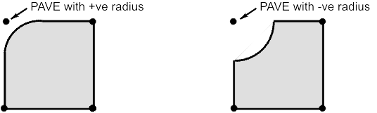
Each Panel Vertex can have an optional Fillet Radius setting which represents a circular arc which curves towards (positive radius) or away from (negative radius) the vertex position, as shown:
The default radius of zero denotes a point.
1974 to current year.
AVEVA Solutions Limited and its subsidiaries. All rights reserved.