Structural Design
User Guide
Section Tools : Utilities
When a section that owns Secondary Nodes is repositioned or extended, it is possible that the secondary nodes may become misaligned. On the SECTIONS tab, in the Tools group, click Utilities, select Align Snodes to correct this. The node(s) are realigned with their attached member(s) by this functionality and it may be executed from SCTN, STRU, ZONE, SITE level or JLDATUM elements owned by a GENSEC (when attached sections are moved), which includes JDATUM on the curve of a GENSEC.
To merge the section end into a selected compound joint, on the SECTIONS tab, in the Tools group, click Utilities, select Create Compound Joint from the drop-down list. The user is prompted to ‘Pick section end to be merged into the compound joint’. The section is highlighted in the 3D view, press Esc. The following Confirm window is displayed:
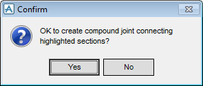
Click Yes to create compound joints.
Click No to discard any inputs and close the window.
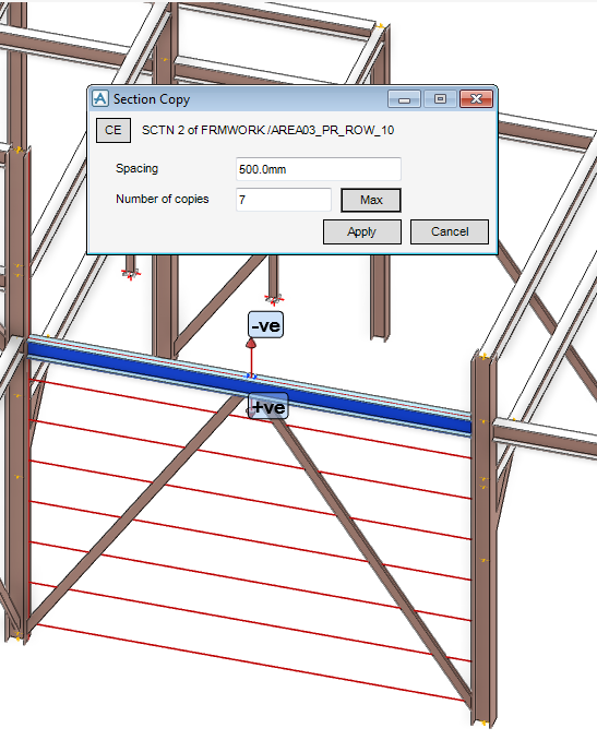
On the SECTIONS tab, in the Tools group, click Utilities, select Multiple Attached Sections from the drop-down list to display the Section Copy window. By default the Spacing is 1000.00mm and the Spacing is 0.
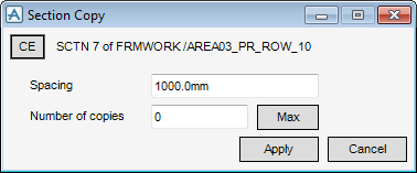
From the Section Copy window, select CE to identify the required element in the 3D graphical design as the CE.
The Section Copy window is automatically populated with the number of copies with the specified spacing that be accommodated.
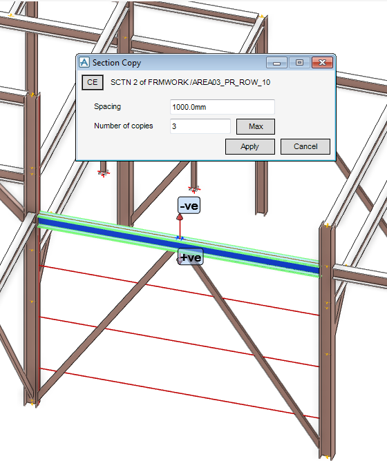
The spacing can be modified to accommodate more or less copies, input the spacing inot the Spacing field, then click Max. The maximum number of copies which can be accommodated is recalculated based on the length of the shortest owning section.
On the SECTIONS tab, in the Tools group, click Utilities, select Regular Structure from the drop-down list to display the Regular Structure window is displayed.
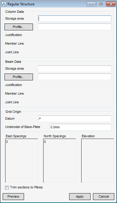
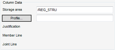
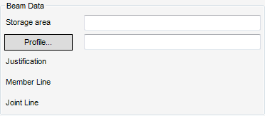
In the Column Data part of the Regular Structure window, input the name of the storage area element (location to storage the regular structure elements).
The specification of the profile(s) used in the regular structure, click Profile to display the Section Specification (Form) window.
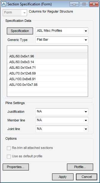
The functionality available to the user is identical to that available from the Default Specification window, refer to Default Section Specification for more information.
The specification of the profile(s) used in the regular structure, click Profile to display the Section Specification (Form) window.
The functionality available to the user is identical to that available from the Default Specification window, refer to Default Section Specification for more information.
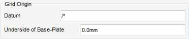
The Grid Origin part of the Regular Structure window is populated with datum and elevation for the grid which is used as a design aid.
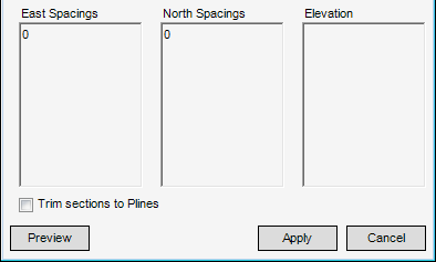
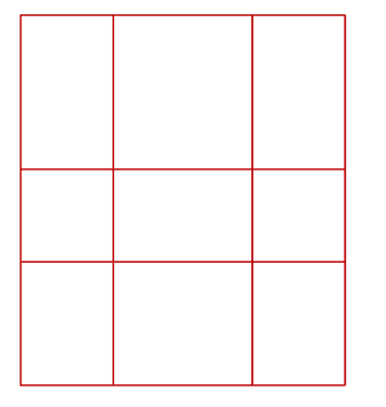
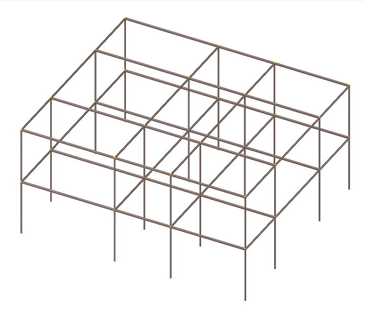
Click Preview to display a single line representation of the structure in the 3D view.
Click Apply to create the regular structure.
On the SECTIONS tab, in the Tools group, click Utilities, select Tower Structure from the drop-down list to display the Tower Structure window is displayed.
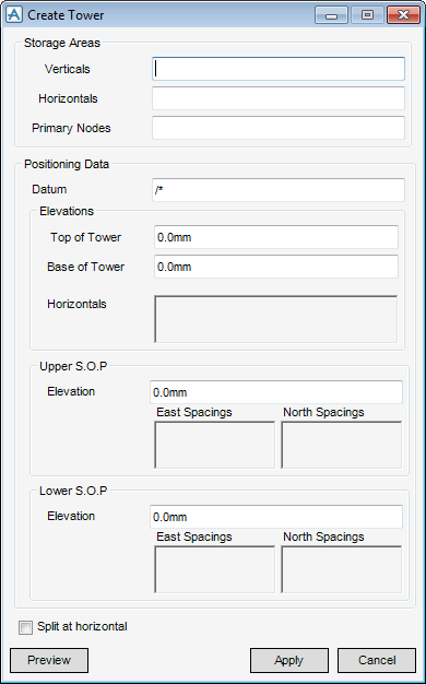
In the Storage Areas part of the Create Tower window, input the name of the storage area element (location to storage the vertical, horizontal and primary nodes elements).
The Positioning Data part of the Create Tower window specifies the datum, elevations, lower and upper setting out points (S.O.Ps).
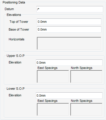
The Top of Tower and Base of Tower elevations are the start and end elevations for the legs of the tower and are relative to the datum.
The Horizontals part of Positioning Data dare populated with the elevations at which horizontal members connecting the legs are created. Any elevations outside the top and base of tower elevations are ignored, all elevations are absolute.
The Upper S.O.P and Lower S.O.P parts of Positioning Data are the points which specify the vectors on which the legs are to be constructed. The east and north spacings are measured from the last position.
Select the Split at Horizontal check box to split the legs of the tower at each horizontal elevation specified in the Horizontals part of Positioning Data.
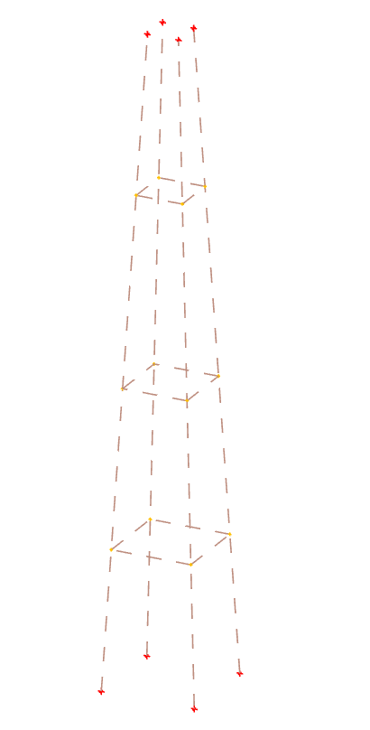
Click Preview to display a single line representation of the structure in the 3D view.
Click Apply to create the tower.