Structural Design
User Guide
Section Tools : Bracing
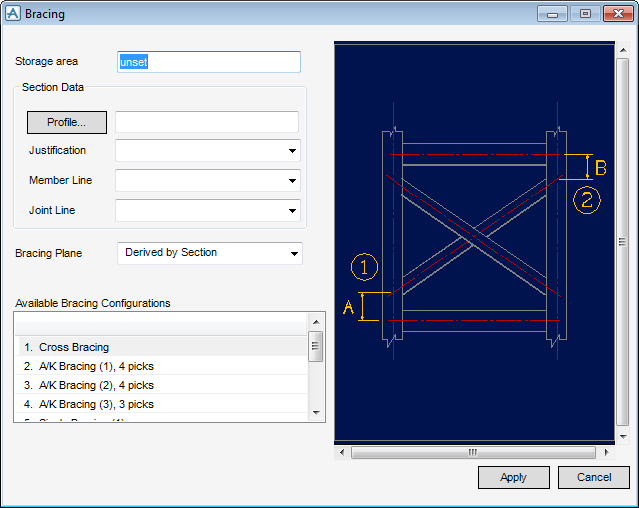
On the SECTIONS tab, in the Tools group, click Bracing, select Bracing Configuration from the drop-down list to display the Bracing window.
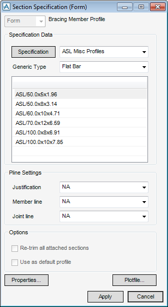
In the Section Data part of the Bracing window, allows the user to define the profile, specification and attributes for the bracing configuration (replacing the default specification). Select Profile to display the Section Specification (Form) window is displayed.
The functionality available to the user is identical to that available from Sections Settings, refer to Default Section Specification for more information.
From the Bracing Plane drop-down list select a design aid for the creation of a bracing configuration:
|
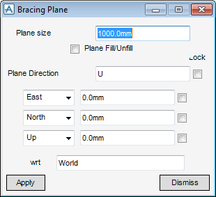
Allows the user to define the bracing plane explicitly and projects the selected points onto the defined plane. The Bracing Plane and Positioning Control windows are displayed.
|
In the Available Bracing Configurations part of the Bracing window is populated with the supplied standard bracing configurations along with a parameterised graphical representation of the configuration.
Click Apply to create the Bracing Configuration, depending on the selection made in the Available Bracing Configurations window determines the window displayed to the user.
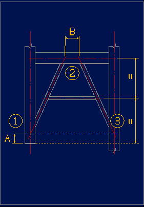
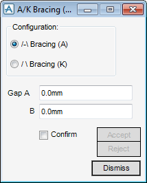
From the Configuration part of the A/K Bracing window, select the required configuration, by default Bracing A is selected.
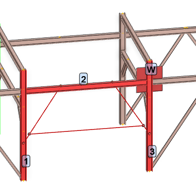
If required, input the initial gap into the Gap A and B fields, refer to the 3D representation for reference.
If the Confirm check box is selected, design aids represent the bracing plane and elements are displayed.
The user is prompted to ‘Pick first section’, the 3D representation on the Bracing window can be used as a guide.
Click Accept to create the bracing configuration.
Click Reject to discard the bracing configuration.
When the user is satisfied with the configuration shown in the 3D view, accept the creation of the sections which forms the bracing members and then click Cancel to close the Bracing window.
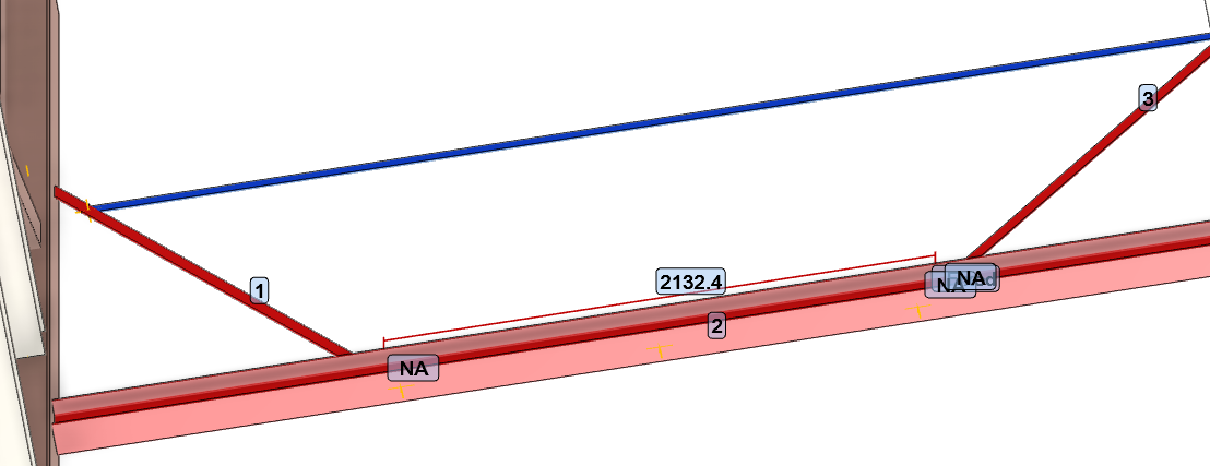
As part of the design process, once bracing configurations have been created the bracing gaps may require adjusting. On the SECTIONS tab, in the Tools group, click Bracing, select Bracing Gaps from the drop-down list to display the Bracing Gaps window.
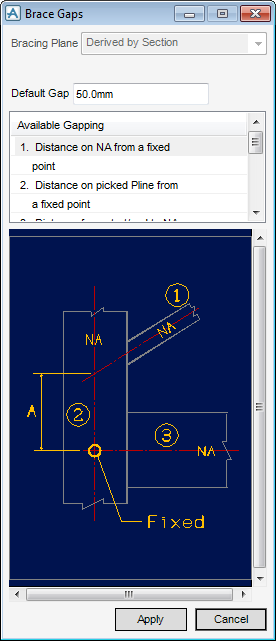
The Brace Gaps window is populated with all the available gap types which can be modified, along with the default Gap and a graphical representation of the Brace Gap. Select the required gap type and default gap, click Apply, the Brace Gap(s) window is displayed.
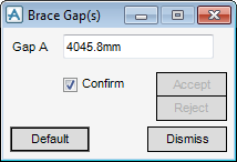
From the Brace Gap(s) window, use the 3D representation window as a guide, the default is displayed in the Gap A field.
By default the Confirm check box is selected, design aids represent the bracing plane and elements are displayed in the 3D view.
The user is prompted to ‘Pick first section end’, use the 3D graphical representation as a guide.
Click Accept to create the bracing gaps.
Click Reject to discard the bracing gaps.
When the user is satisfied with the configuration shown in the 3D view, accept the creation of the sections which forms the bracing members and then click Cancel to close the Bracing Gap(s) window.

