Structural Design
User Guide
Section Tools : Split Sections
It is often easier to model an overall structure and then split it into smaller components for fabrication or assembly purposes. The split utility allows Sections, Generic Sections and Panels to be split from the Beams and Columns or Panels and Plates applications.
From the Beams and Columns application main menu bar, select Modify > Sections > Split to open the Split Steel window.
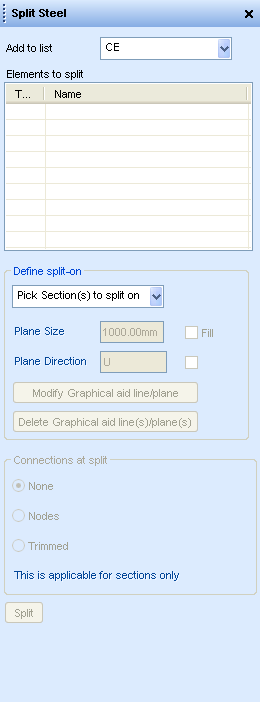
The elements to be split are added to the Elements to split list with the options available in the Add to list drop-down menu.

|
Note:
|
Right click anywhere in the Elements to split list, even if the list is empty, and a drop-down menu is displayed with the same selection options as those described above. However, the CE Members option is not included.
Once the beam(s) to be split has been added to the Elements to split list, where it is to be split must be specified.
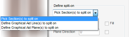
The Define split-on area of the window has an options list with these options:
|
Allows the user to graphically select one or more sections to be split on from the graphical view. When this option is selected the prompt ‘Pick a selection to split on:’ is displayed. One or more sections may be selected, the selection process is terminated when Esc is pressed.
|
These options activate the Positioning control toolbar. The exact prompts for these options depend on the Pick Method set on the Positioning control toolbar.
|
Allows the user to select points in the graphical display to create one or more aid lines to split on by selecting points in the graphical display. When this option is selected the prompt ‘Line start (Snap) Snap:’ is displayed. One or more lines may be created. Press Esc to terminates the creation process.
|
|
The Plane Size and Plane Direction textboxes are activated in the Define split-on area of the window as are the check boxes adjacent to them.
The user is prompted to ‘Pick to position plane (Snap) Snap:’. One or more planes may be created, the Plane Size and Plane Direction are set before the next plane is created. Press Esc to terminate the creation process.
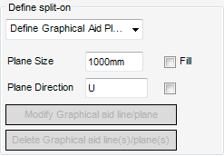
Once graphical aid lines and /or planes have been defined the Modify Graphical aid line/plane and Delete Graphical aid line(s)/plane(s) are enabled.
Click Modify Graphical aid line/plane the user is prompted to ‘Pick aid to be modified pick Aid:’ Picking a line or plane from the graphical view displays the appropriate aid modification window, that is Modify Line or Modify Plane.
Click Delete Graphical aid line(s)/plane(s) the user is prompted to ‘Pick aid(s) to be deleted. <esc to finish> pick Aid:’. One or more lines or planes may be selected for deletion. Press Esc to terminate the selection process.
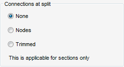
The Connections at split area of the window allows the user to define what happens to the sections at the split. Only SCTN elements only have this functionality.
If the Pick Section(s) to split on option is selected the Connections at split options of the Split Steel window becomes active.
|
•
|
None - the section is split at the Justification line of the section it is split on. However, there is no connectivity created between the sections.
|
|
•
|
Nodes - the section is split at the Justification line of the section it is split on. SNOD and SJOI elements are created which connect the split sections to the section(s) they were spilt on.
|
|
•
|
Trimmed - the section is split at the Justification line of the section it is split on. SNOD and SJOI elements are created which connect the split sections to the section(s) they were spilt on. The split sections are trimmed to the Pline at the extremity of the section(s) they split on.
|
When all options have been selected or set, click Split to split the elements.