Structural Design
User Guide
Section Tools : Extend
The Extend By functionality allows the user to lengthen or shorten the section by moving its Start or End position by a specified amount.
On the SECTIONS tab, in the Tools group, click Extend, select By from the drop-down list to display the Extend Section - Explicit window is displayed.
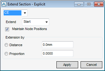
A label in the 3D view is placed at either end of the section to identify the Start and End locations. The Extend drop-down menu allows the user to select which end of the section is extended, the choices are Start, End or Pick.
If the Pick option is selected the user is prompted to select the end of the section that is re‑positioned when the Apply is selected.
The user can move the end of a section either by Distance or by a Proportion of the sections current length, by selection of the appropriate option and entering the required value. Entering a positive value lengthens the section and entering a negative value shortens it.
To maintain the position of any Secondary Node owned by the section, select the Maintain Sections’ Node Positions checkbox.
Extend Through window allows the user to specify a plane, position and orientation to extend either end of the section to. The section only extends along its Z axis, that is its extrusion direction, as the plane is infinite in its planar dimensions.
On the SECTIONS tab, in the Tools group, click Extend, select Through from the drop-down list to display to display the Extend Section - Relative window.
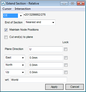
The End of Section list allows the user to specify which end of the section is extended (or trimmed) to the plane. Four choices are available:
|
•
|
Nearest end – The default setting. The end of the section nearest to the plane is repositioned.
|
|
•
|
Start – The start position of the section is moved.
|
|
•
|
End – The end position of the section is moved.
|
|
•
|
When the Extend Section - Relative window is displayed, a label is placed at each end of the section to identify which end is the Start and which is the End.
The user can define the plane position explicitly by entering co-ordinates in the Plane Direction East/West, North/South and Up/Down fields of the window, or with the Cursor and Intersection functionality and selection of the position in the 3D view.
The Plane Direction is set by default to Up, however any direction can be entered to orientate the plane.
The Plane Direction has been set to S. The plane aid and direction vector displayed helps the user visualize the position and direction of the plane.
Click Apply to extend the end of the current element to the plane. The position of any Secondary Nodes owned by the section is measured from its start position. Select the Maintain Sections’ Node Positions checkbox to make sure the Secondary Nodes stay in their original position when the start position of the section is moved. Otherwise, the Secondary Nodes move with the start position, that is their Z distance attribute are maintained.
Select the Cut end(s) to plane checkbox to orientate the end of the section to the plane direction after it has been extended or trimmed.