Structural Design
User Guide
Walls and Floors Options : Options
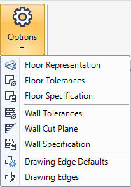
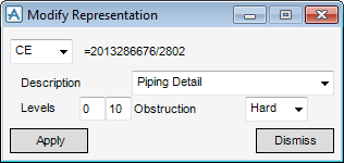
The representation of a floor element can be modified from its representation defaults. On the WALLS AND FLOORS tab, in the Settings group, click Options, select Floor Representation from the drop-down list to display the Modify Representation window.
From the Modify Representation window, the user can modify the level and obstruction which affect the way elements are displayed in the 3D view and how they are dealt with when checking for clashes between design elements.
The Panel/Floor Tolerances govern the tolerances (clearances) of the panels and floors elements. On the WALLS AND FLOORS tab, in the Settings group, click Options, select Floor Tolerances to display the Panel/Floor Tolerances window. The functionality available to the user is identical to that available from Panel Tolerances, refer to Panels Tolerances.
On the WALLS AND FLOORS tab, in the Settings, click Options, select Wall Specification to display the Floor/Screed Specification (Default) window.
All the tasks that a user would carry out that are associated with the default specification are initiated from the Floor/Screed Specification (Default) window. The functionality available to the user is identical to for the other three applications. Refer to Default Section Specification.
The standard default is for joints to be subordinate. The default can be changed by the selection of Section tolerances.
On the WALLS AND FLOORS tab, in the Options group, click Tolerances to display the Wall Tolerances window.
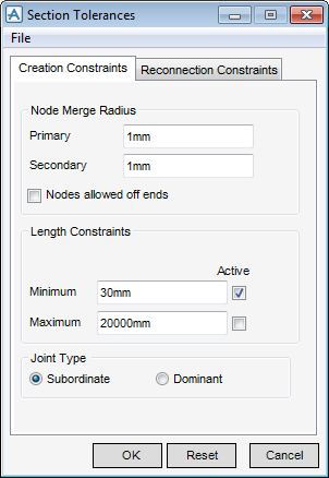
The functionality available to the user is identical to that described in Sections, refer to Section Tolerances.
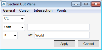
The user can specify with the start or end of the wall’s cut plane with the use of selection functionality, on the WALLS AND FLOORS tab, in the Options group, click Wall Cut Plane to display the Section Cut Plane window.
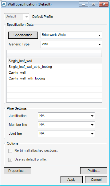
On the WALLS AND FLOORS tab, in the Settings, click Options, select Wall Specification to display the Wall Specification (Default) window.
All the tasks that a user would carry out that are associated with the default specification are initiated from the Wall Specification (Default) window. The functionality available to the user is identical to for the other three applications, refer to Default Section Specification for more information.
The Draft Edge Defaults window is populated with the defaults governed by the default specification. From the WALLS AND FLOORS tab, in the Options group, click Draft Edge Definition, to display the Draft Edge Definition window.
The functionality available to the user is identical to that described in Panels, refer to Draft Edges.
The Draft Edge window is populated with the defaults governed by the default specification. From the WALLS AND FLOORS tab, in the Options group, click Draft Edge, to display the Draft Edge window.