Structural Design
User Guide
SDNF Export/Import : Export to SDNF
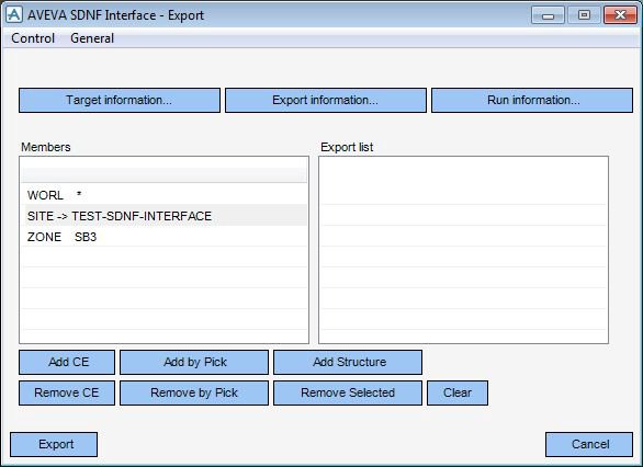
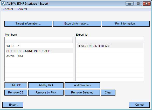
To export a steel structure to a SDNF file, on the Sections, Plates or Stairs Ladders Handrails tab, in the SDNF group, click Export to display the Export window.
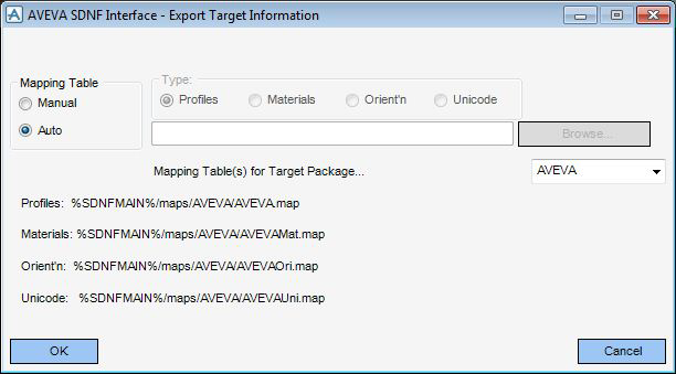
Clicking Target Information displays the Export Target Information window which contains information about the 3D steel detailing package which the SDNF file is being transferred to.

The interface requires at least two external mapping tables for each Target Package to check that the Target Package can accept the data. It also may use the Profile Orientation and/or the Unicode mapping tables if necessary. The main mapping tables are for the Steel Profiles, Materials and for mapping the Profile Orientations between AVEVA E3D™ and the neutral file. The Unicode mapping table is to translate AVEVA E3D™ Unicode strings into ASCII strings according to the SDNF Format Specification. The section Customise SDNF tells the user how to arrange these files on their file system and what format they are to be. The interface also needs to know where the external mapping files are located on the users computer network. For this, internal mapping tables are required. Refer to Internal Mapping Files which explains how to configure the interface to tell it where all the files are located.
The current file settings are indicated on this Export Target Information window. Changing the Target Package by using the Target Package selector button on the right-hand side of the window may cause the text to change giving the full path names of the respective files. Do not be concerned that the path name may be truncated by the insertion of the ellipsis (…): it is modified only for display purposes on the window.
The system also checks that these files are compatible with the Target Package by checking the identification line at the top of each mapping table. Refer to External Mapping Files for details about the format of these mapping files.
The two main options are, Auto and Manual which are activated by selecting the appropriate radio button.
Auto causes the interface to select automatically the mapping tables for the Target Package indicated by the Target Package selector gadget on the right hand side of the window, according to the system configuration files.
Manual activates other buttons, which are greyed out for the Auto option. Selecting this option changes the window to be similar to below.
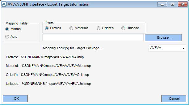
The user can select the file type using the Profiles, Materials, Orient'n or Unicode radio buttons and enter the full path name of the file in the data entry area. The user can also include system environment variables in the path name as long as they are in the proper AVEVA E3D™ format, e.g.%ENVVAR% being the AVEVA E3D™ representation of the ENVVAR environment variable.
The user can either choose by hand which mapping file to use by entering its name in the text data entry field, or by using the Browse option to bring up a File Browser. The user may use this browser to search for the relevant mapping file.
Once the user has entered all the correct data on the Export Target Information window, click OK and the interface variables will be updated. Clicking CANCEL will close the window, leaving the original interface variables unchanged.
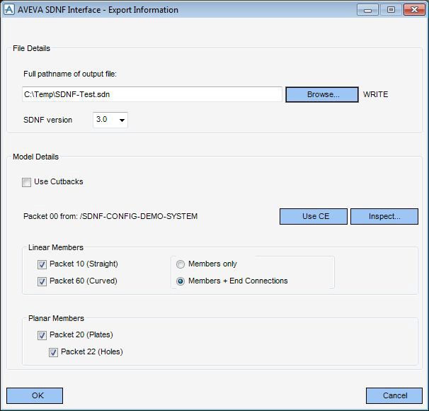
On the Export Information window there is a drop-down list which the user can use to select which SDNF version to output.
Clicking Export Information displays the Export Information window which contains information about the export process.
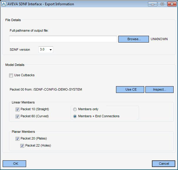
The user can either type the full folder path name of the output file, or click Browse to display a File Browser. The interface tests to see if the file exists and if it does, the user will be asked whether to overwrite it. If the file does exist and the user wants to overwrite it, the file mode beside Browse will change from WRITE to OVERWRITE. The output file is rechecked for write/overwrite status during the actual Export process. This is because the user can perform repeat Exports without changing the output file name.
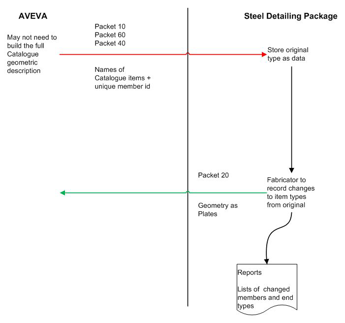
The SDNF file may have several sections: a header, Packet 00; a set of Linear Members, Packet 10; a set of Plates, Packet 20 and their holes (Packet 22); a set of Connection Details, Packet 40, and a set of Arc Members (Packet 60). The header is compulsory: any other Packets are optional.
Selecting the information to be contained in Packet 00 is performed by navigating to, or below, the relevant AVEVA E3D™ Design SITE, ZONE or STRU element which contains the required header information. This is done by using the Members list window on the main Export window. When at, or below, the correct element, click Use CE on this window and the source text will indicate from where the interface will get the information. If there is not enough space on the window the element's reference number is output rather than its name.
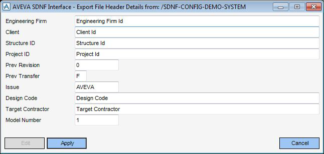
The user can view the information contained by the chosen header element by clicking Inspect which displays the Export File Header Details window.
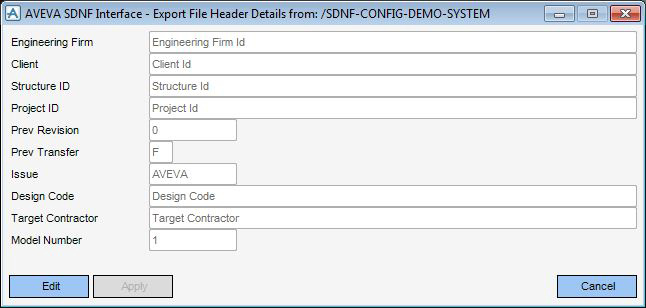
At first the entry fields are greyed out but the user can read the contents. To modify the contents of the fields click Edit on the Export File Header Details window and the fields become active allowing the user to enter any revised data. Click Apply and the data will be transferred back to the chosen header object, overwriting the original data. Clicking Cancel will leave all the data unchanged.
Using the toggles on the Export Information window, the user can select whether to export Packet 10 (Straight), Packet 60 (Curved) or Packet 20 (Plates) with the option of their holes, Packet 22 (Holes). The user cannot output Packet 40 (End Connections) without outputting either Packet 10 (Straight) or Packet 60 (Curved). If the user wants neither Packet 10 nor Packet 60, the sub-options, Members only and Members + End Connections are inactivated and greyed out. Similarly, one cannot output Packet 22 (Holes) without outputting Packet 20 (Plates). But the user will be able to export Plates without their holes.
Once all the correct data has been entered on the Export Information window, click OK and the interface variables will be updated. Clicking CANCEL will close the window, leaving the original interface variables unchanged.
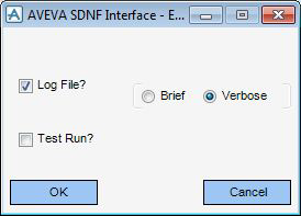
Clicking Run Information displays the Export window which allows the user to view the Log File after the export process is complete by clicking the Log File? check box.
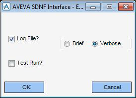
Clicking either the Brief or Verbose radio buttons the user can choose which format messages are displayed.
The Test Run? option allows the user to suppress the updating of all the Export flags. This is so that the user can see if there will be a successful Export of the model. The user may find that the Profile or Material mapping files are not quite up to date which might cause a failure in the Export process. Therefore, the user can select this option to define this as a test run.
After the Export process has completed, Test Run? is reset to false. This is so that the user is forced to state categorically each time the model is Exported that the run is a trial.
Once all the correct data has been entered on the Run Information window, click OK and the interface variables will be updated. Clicking CANCEL will close the window, leaving the original interface variables unchanged.
The user must enter the elements to be exported, but need not select only SCTNs (Straight Members), GENSECs (Curved Members), or only PANEs (Plates). The interface will locate all SCTNs, GENSECs and PANEs contained in, or implied by, the Export list. If the user adds something to the Export list and has the item on display in a 3D Volume View it will be enhanced by changing its colour. The Export list is managed such that duplicate elements are removed and that items are exported only once.
|
Note:
|
Add CE just adds the current element to the list. This also implies all items below the current element in the database hierarchy. The WORL can not be added to the list.
The Add by Pick option allows the user to select an item from the 3D Volume View. It is similar to other Design pick functions. Selecting this option brings up a Status window and puts the user into a mode where an item from the 3D Volume View can be picked. The user can also pick a sequence of items in succession to add to the Export list. Click the Esc key when complete. If the user does not want to continue, click the Esc key.
Add Structure will attempt to climb to the Structure owning the current element and add that to the Export list. A warning will be displayed if there isn't an owning Structure.
There is also a set of methods by which the user can remove items from the Export list. These options work only on entries in the Export list, rather than in the model. As with adding to the Export list, removing from the Export list will cause the item or items removed to be returned to the default colour as defined by this interface.
Remove CE looks for the name of the current element in the list and removes it if present.
Remove by Pick allows the user to select something from the 3D Volume View and, if it is present in the Export list, the name will be removed. As with the Add by Pick option, the user may select a series of items to attempt to remove from the Export list until the Esc key is clicked.
Remove Selected is a means by which the item selected in the Export list is subsequently removed. Select the item first in the list, then click Remove Selected.
Clear just removes everything from the list.
Cancel closes the AVEVA SDNF Export window.
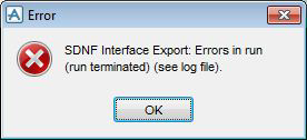
Export executes the Export process. As it proceeds the user is kept informed of the progress by means of messages at the bottom of the main Design window as well as by forms and prompts.
The Control drop-down menu has two options; Re-initialise and Exit. Changing any mapping files or any other variables, Re-initialise will reload these files to save the user having to rebuild the whole user interface from scratch. The Exit command will remove all forms and menus and global variables associated with the interface.
The General drop-down menu has one option, Highlight which displays the Highlighter window enabling the user to identify new, changed and deleted items in the model. This has more relevance to the Import process and is described in more detail in Highlighting Changes in the Design.
All reference data, such as any pre-existing reference model, is removed before exporting anything. Refer to Import from SDNF on Importing for details about saving the reference model.
In addition, there is an SDNF specific UDA, :SDNFEXCLUDE, attached to certain AVEVA E3D™ elements by which the user can define whether the item is to be exported or not. Setting this logical flag to true will exclude the item from the Export process. Refer to UDAs.
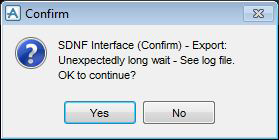
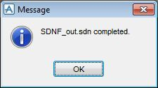
Click YES and the interface will wait for another period of time. Clicking NO will cause the interface to stop where it is. Finally the system will indicate its completion, whether successful or not. This completion message should be read in conjunction with the log file, if any errors are indicated.
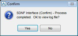
On completion of the external program, the status file is inspected and, if the result is favourable, the user will then be asked whether or not to view the log file, if that option has been selected on the Run Information window.
To inspect the log file later, save it with the File > Save as option in the SDNF File Viewer window which will bring up a File Browser, or by clicking Save as to the suggested filename. Either way, if the file already exists, the user will be asked whether to overwrite it. The log file window may then be closed by clicking Cancel.
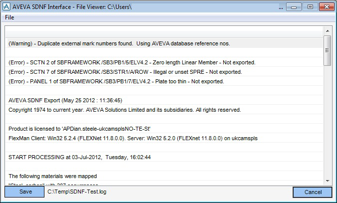
If the Brief mode has been chosen on the Run Information window for displaying the log file, the window displaying the log file will filter out all Warning messages, leaving only the Error messages. Saving the log file, however, all messages will be retained in the file.
Panels in AVEVA E3D™ are to be transferred as Plates using Packet 20. This will cover stiffeners, floor and toe plates. Bent plates will also be transferred if they are expressed as their component flat plates. If Bent Plates are to be treated as Angle linear members then they should be modelled as such.
If the AVEVA E3D™ Design Penetration Application is used to generate Catalogue holes, the resultant holes, kicker plates and stiffeners will not be exported because they are contained in a Catalogue definition. Some holes and negative primitives can be transferred from the design. See next section.
End connections and base plates will be modelled in Design Catalogue items and transferred to the SDNF file using end coding information stored in the CTYA attribute of the Catalogue component. A mapping table is required to enable the information to be transferred in order that a corresponding entity to be created in the external 3D steel detailing package. Once the end has been detailed, the resultant geometry may be returned to Design as Plate members in Packet 20 for graphical and clash checks. In AVEVA E3D™ Joint selection is controlled by specification.
The following test can be performed after installing the AVEVA SDNF product to make sure that the installation is complete and correct. All the required testing material can be found below the sub-folder SDNF\test\results\export in the user data folder.
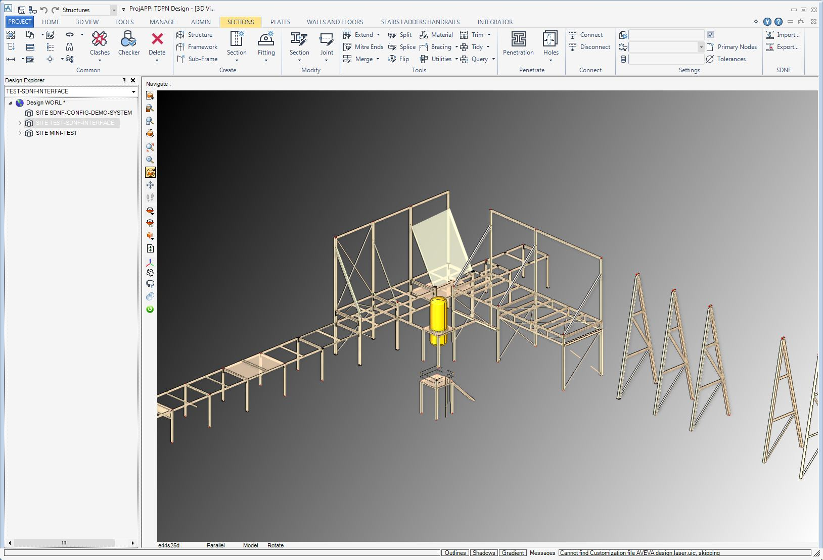
When that is finished, bring the SITE into view by adjusting the view limits in the 3D Volume View window.
Change the view in that window by selecting the 3D VIEW tab, in the Manipulate group, select Isometric and select Iso 3 from the list.
On any sub tab page of the Structural discipline ribbon bar, select the SDNF Export option which will bring up the main AVEVA SDNF Export window.
Click Target information on the AVEVA SDNF - Export window to display the Export Target Information window.
Select the Auto mode toggle option and select "AVEVA" from the list of Target Packages on the Target Package selector gadget on the right hand side of the window. This causes the system to automatically detect the Target Package's Profile mapping table and Material mapping table.
Click Export information on the AVEVA SDNF - Export window to display the Export Information window.
Check that the SDNF file header (Packet 00) is coming from /SDNF-CONFIG-DEMO-SYSTEM. Use the navigator and browser if necessary.
Select which SDNF Packets to export: Packet 10 (Straight), Members + End Connections and Packet 20 (Plates). Select SDNF version 3.0.
Do not select the Test Run? option as this is not a test run.
To add the SITE to be exported to SDNF, Select SITE /TEST-SDNF-INTERFACE in the form's Members list. Click Add CE. This will cause all the members in the 3D Volume View window change colour to indicate they are being exported.
When the process is complete, the user will be asked whether to inspect the log file. The user can then save it with the File > Save as option on the SDNF File Viewer window to bring up a File Browser, or by clicking Save as to the suggested filename. The log file window can then be closed by clicking Cancel.
Checking the SDNF Output File
Compare the SDNF-Test.sdn file produced with the one supplied in the test/results/export folder.