Structural Design
User Guide
Modify Walls and Floors : Modify Floor/Screed Definition : The Loop Vertex Editor Window
In the model explorer or 3D view, select the floor/screed element to be modified as the CE. On the WALLS AND FLOORS tab, click Modify, select Definition from the drop-down list to display the Loop Vertex Editor window.
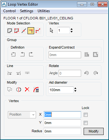
From the Loop Vertex Editor window, the user can select these options:
|
When Confirm is selected the user must click Modify at the bottom of the window to implement each modification. When Confirm is not selected each modification is implemented immediately.
|
|
|
When Confirm is selected the user must confirm each deletion in order to complete the command. When Confirm is not selected deletions are implemented immediately.
|
|
|
When Tag Edges is selected each edge is tagged with the number of the vertex at its start.
|
|
|
When Display Axes is selected the axes of the floor/screed are displayed at the first vertex.
|
|
|
When Free rotate is selected groups of vertices can be orientated automatically when moved from one edge to another.
|
|
The options in the Mode Selection pane of the Loop Vertex Editor window allow the modification of a single vertex, an edge or a group of vertices:
|
Allows the selection of an edge to be modified. The adjacent Edge area shows the current edge number.
|
|
|
Allows the selection of a vertex to be modified. The adjacent Vertex area shows the current vertex number.
|
|
The Vertex/Edge pane of the Loop Vertex Editor window, contains a Select option and a counter that shows the current vertex or edge depending on the current mode. If Select edge to modify is selected, the counter label changes to Edge and the counter shows the current edge.
The Select vertex/edge option allows the user to pick a vertex in the graphical display. The adjacent Vertex/Edge counter shows the current vertex/edge number which is also tagged in the 3D view. The user can navigate to a specific vertex or edge by typing its number in the text box or by using the up/down arrows to step through the list.
When a group of vertices are modified, the options in the Group pane of the Loop Vertex Editor window become active. These allow the modification of the current group:
The Expand/Contract area expands or contracts a group as specified.
The Expand Group moves each edge of the group outwards by the distance specified in the Expand/Contract text box normal to its own direction.
The Contract Group moves each edge of the group inwards by the distance specified in the Expand/Contract text box normal to its own direction.
If an edge is modified, the functionality in the Line area become active. These options allow the modification of the current edge in these ways:
|
Moves the Start vertex along the edge direction to align it through a picked position. Use the Positioning Control toolbar options to pick the required position. Alternatively, if a line is selected the End vertex is moved along the edge direction until it intersects the picked line. These operations can change the edge length.
|
|
|
Moves the End vertex along the edge direction to align it through a picked position. Use the Positioning Control toolbar options to pick the required position. Alternatively, if a line is selected the Start vertex is moved along the edge direction until it intersects the picked line. These operations can change the edge length.
|
|
The options in the Rotate pane of the Loop Vertex Editor window allows the rotation of groups of vertices in these ways:
Rotate anticlockwise rotates the edge anticlockwise, through the rotation angle specified in the Angle textbox, about the reference end. The operation maintains the edge length.
Rotate clockwise rotates the edge clockwise, through the rotation angle specified in the Angle textbox, about the reference end. The operation maintains the edge length.
The options in the Modify pane of the Loop Vertex Editor window enables the user to carry out these operations on the current group selection:
|
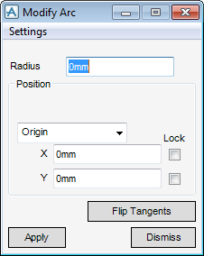
Manipulates a fillet arc at the current loop vertex. When selected the Modified Arc window is displayed and the Loop Vertex Editor window becomes temporarily inactive.
|
The pane of the Loop Vertex Editor window displays co-ordinate data about the current vertex, edge or group depending on the Selection Mode.
For an edge the co-ordinates are given for the start or end of the edge. An aid is displayed in the graphical view showing which is the start and which is the end. By default the START edge is shown in uppercase and the end is shown in lowercase. Only the START is affected by any modifications made to the currently displayed co-ordinates.
Select End to display the END of the edge in uppercase and the start in lowercase. Modifications made to the currently displayed co-ordinates only affect the END.