Structural Design
User Guide
Modify Sections : Modify Joint
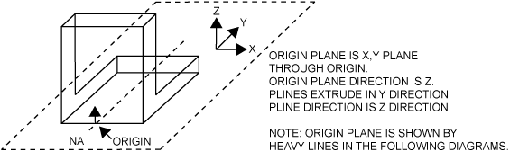
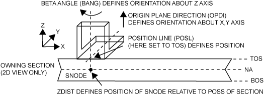
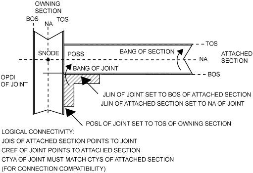
How the origin plane of the Joint is set with reference to the Owning Section (via the POSL attribute), while its position within the constraints of that plane is set with reference to the Attached Section (by aligning the plines defined by the JLINs of both Joint and Section). That is, with reference to the orientation of the diagram, to move the Joint horizontally change its POSL and vertically change its JLIN. Both the Section and the Joint can be rotated independently by changing their BANGs (the Section rotates about its NA, the Joint about its OPDI).
From the SECTIONS tab, in the Modify group, click Fitting. The user is prompted to A Joint Specification window is displayed for the joint to which the picked section end is attached.
|
Note:
|
The user can apply a Joint Specification to the connected end of a GENSEC element. Click CE to load the current element (only if the element is a FIXING) to the Joint Specification window.
|
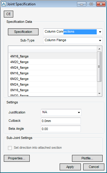
The method of selection from the available joint specifications is the same as that used to select section profiles. In this case select Column Connections, Column Flange, 6M24_flange and leave all other form settings at their defaults.
Click Properties. A subsidiary Modify Properties window is displayed which allows the user to specify some local dimensional data for the selected type of joint.
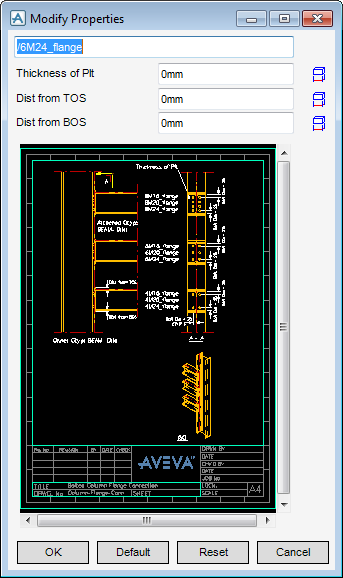
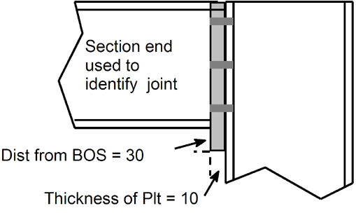
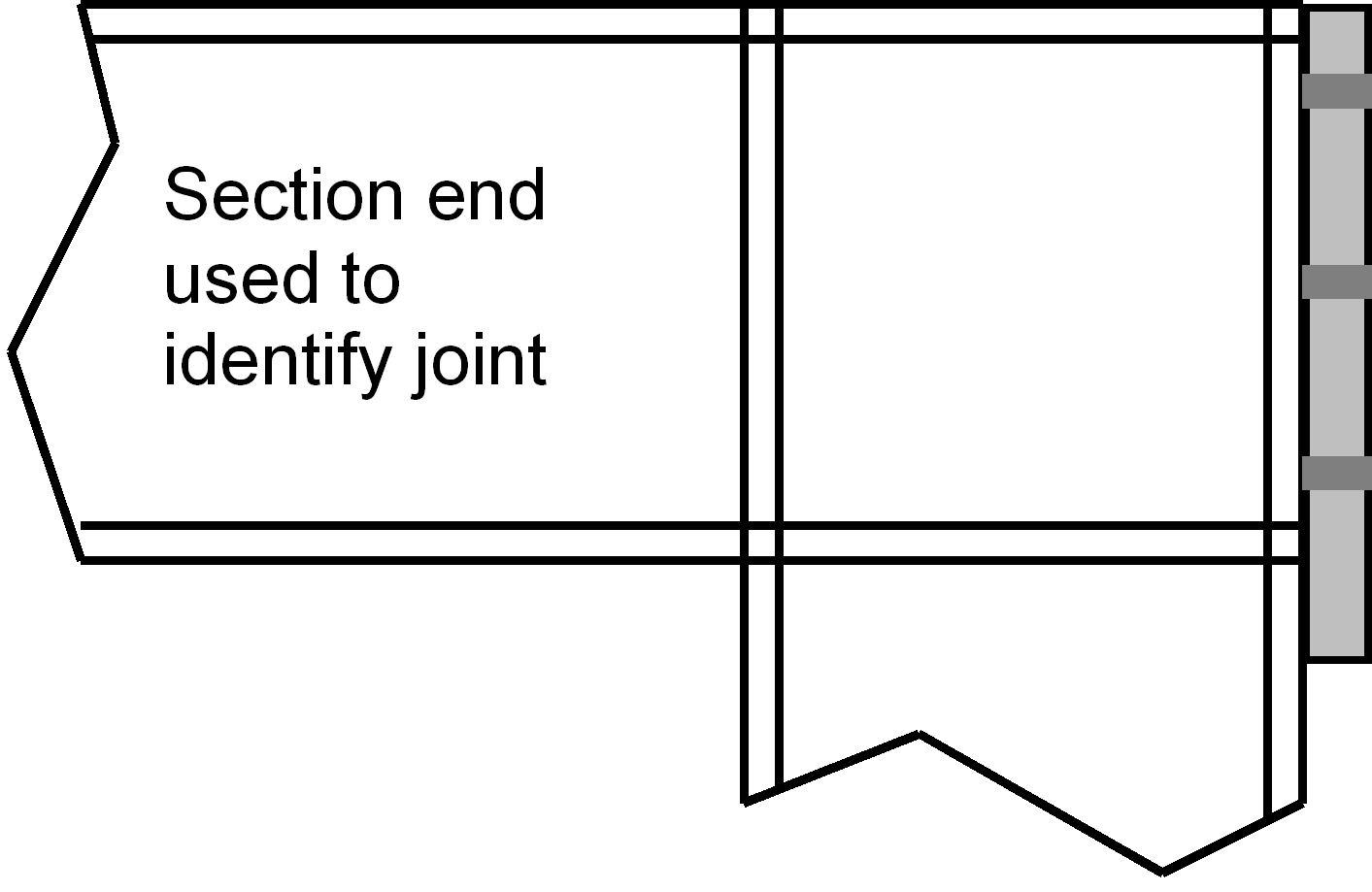
For this joint set Thickness of Plt, Dist from TOS, and Dist from BOS. Click OK to close the Modify Properties window and Apply the Joint Specification window to complete the setting of the joint specification. (The geometry of most types of joint can be modified via appropriate entries in a window such as this. How the catalogue has been set up can affect this.)
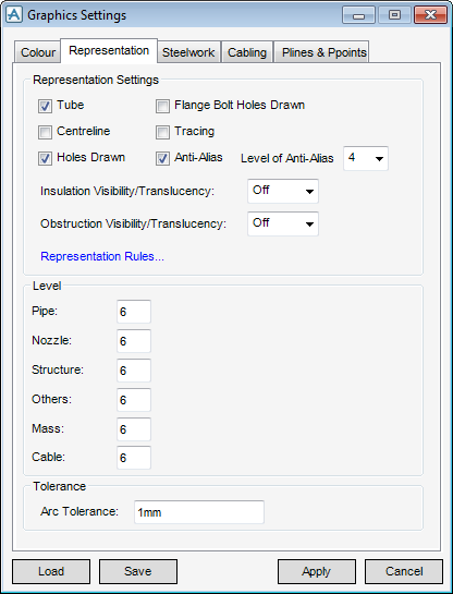
On the Representation tab, select the Holes Drawn checkbox. Click OK to apply the setting and close the window.
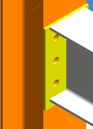
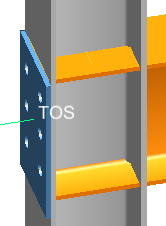
Zoom in close to the beam end to see what the joint looks like. The height and width of the endplate are set automatically from the dimensions of the beam and column, respectively, with adjustments to suit the values entered in the Define Properties window. If the joint dimensions in the catalogue are specified as design parameters whose values are derived from the attached and owning sections. The joint displayed as shown:
 |
The position of the joint relative to the profile of the column (its owning section) is determined by the joint’s position line. To see the effect of changing this. On the SECTIONS tab, in the Modify group, click Section, select Joint Line from the drop-down list to display the Joint Line window.
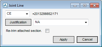
The displayed Position Line window shows the current setting as either BOS or TOS (depending at which end of the beam the joint is situated). Change this to the opposite setting (that is TOS or BOS), select the Re-trim attached section checkbox, and click Apply. The joint and its attached section end move thus:
 |
Reposition the joint correctly, then click Cancel to discard any information and close the Position Line and Joint Specification windows.
.On the SECTIONS tab, in the Modify group, click Joints, select Like Maintain Pline from the drop-down list.
The user is prompted to ‘Identify end of section to be copied like’, pick the same section end as picked previously. When prompted to ‘Identify section end to be modified’, pick the other end of the same beam. Press Escape for both of the next prompts.
|
Note:
|
If the joints were ‘handed’, such as a shelf angle, the user would also see that the second joint has been rotated automatically about its vertical axis to match the start/end directions of the section. The endplate does not show this, on the PROJECT tab, in the Common group, click Attributes, the user is able to see which attributes differ between the two joints. If the user wants to reverse an action, from the Quick Access toolbar, select Undo.
|