Structural Design
User Guide
Modify Panels : Boundary
With the panel to be modified as the CE, from the PLATES tab, in the Modify group, select Boundary from the drop-down list to display the Loop Vertex Editor window.
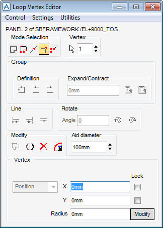
As with many of the windows used in AVEVA E3D™, the Loop Vertex Editor window fulfils several functions. The window is divided into several areas which are described below.
|
When set On the user must select Create or Modify to implement each creation or modification, dependant on which mode is current. When set Off, each creation or modification is implemented immediately.
|
|
|
When set On, the user must confirm each deletion in order to complete the command. When set Off, deletions are implemented immediately.
|
|
|
When set On, each edge is tagged with the number of the vertex at its start.
|
|
When set On this option allows groups of vertices to be oriented automatically when they are positioned relative, to say one edge, and are then moved to a different edge.
|
|
The options in the Mode Selection area of the window allows the user to select a single vertex, an edge or a group of vertices to be modified or create a new vertex.
|
Allows the user to pick an edge to be modified. The adjacent Edge gadget shows the current edge number (for example: the number of the vertex at its start).
|
|
|
Allows the user to pick a vertex to be modified. The adjacent Vertex gadget shows the current vertex number.
|
|
The Vertex/Edge part of the window displays a Select option and a counter that shows the current vertex or edge, dependant on the current mode. If the Select edge to modify is selected, the counter label changes to Edge and the counter shows the current edge.
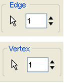
Select vertex/edge allows the user to pick a vertex in the graphical view. The adjacent Vertex/Edge counter shows the current vertex/edge number, which is also tagged in the graphical view. The user can navigate to a specific vertex/edge by typing its number in the textbox or with the up/down arrows to step through the list.
When a group of vertices are modified, the options in the Group part of the window become active. These options allow the user to modify the current group in these ways:
|
Note:
|
|
•
|
Expand group - moves each edge outwards to expand the group area, by the distance specified in the adjacent Expand/Contract textbox, normal to its own direction.
|
|
•
|
Contract group - moves each edge inwards to contract the group area by the distance specified in the adjacent Expand/Contract textbox, normal to its own direction.
|
|
Note:
|
Expand/Contract applies to all edges in the Group and includes those on panel protrusions, and so on, therefore, excessive expansion or contraction may lead to invalid loop geometry.
|
If an edge is modified, the options available in the Line part of the window become active. These options allow the user to modify the current edge in these ways:
The options in the Rotate part of the window allows the user to rotate groups of vertices in these ways:
The options in the Modify part of the window allows the user to carry out these operations on the current Group selection:
|
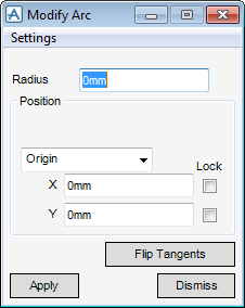
Manipulates a fillet arc at the current loop vertex. When selected the Modify Arc window is displayed and the Loop Vertex Editor window becomes temporarily inactive.
|
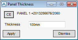
The panel thickness can only be modified if it was left unset in the Plate Specification window, If the thickness was set in the Plate Specification window the Panel Thickness window displays the message Element thickness fixed by specification.
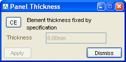
To modify the thickness of a panel, make the panel to be modified the CE. On the Plates tab, in the Modify group, click Panels, select Thickness from the list to display the Panel Thickness window.
Make the panel to be modified the CE. On the Plates tab, in the Modify group, click Panels, select Justification from the list to display the Panel Justification window. Select Bottom, Centre or Top from the Justification drop-down list and click Apply to modify the panel justification.
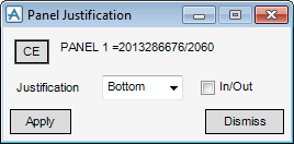
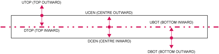
The in/out checkbox enables the user to set the direction relative to the plane used to justify the panel as shown in the diagram.
To see the effects of the change to the justification, on the Plates tab, in the Modify group, click Fitting to display the Modify Panel Fitting window.
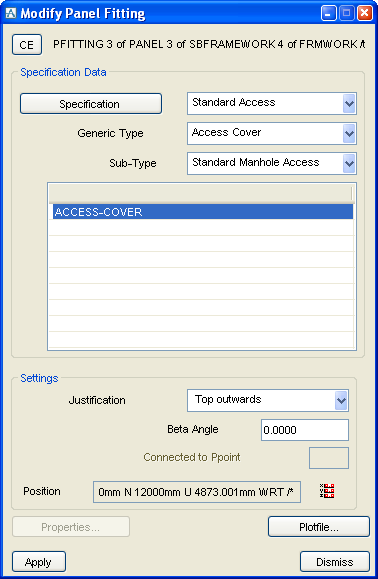
Modify the panel fitting as required, click OK to accept the changes or click Dismiss to discard any information and close the Modify window.
Sections can also own Fittings (FITTs rather than PFITs in this case) which can serve a similarly wide range of purposes. Similar principles apply to their creation and manipulation in the Beams and Columns application, for more information, refer to Some Standard Fittings.