Structural Design
User Guide
Create Wall Fittings : Create Wall Fittings
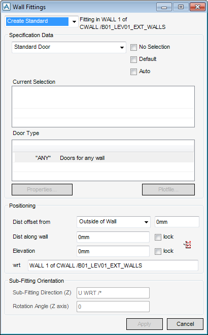
From the model explorer or 3D view, select the wall where the fittings are to be positioned as the CE. On the WALLS AND FLOORS tab, in the Create group, click Wall Fittings to display the Wall Fittings window.
All the tasks that a user would carry out that are associated with the creation or modification of wall fittings are initiated from a central Fittings window which acts as task hub. Dependant on selections made in the Fittings window the user is presented with further windows which prompt user input.
By default the Create Standard option (single fitting) is selected.
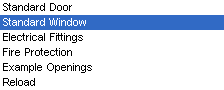
From the Specification Data pane of the Wall Fittings window, by default Electrical Fittings is selected. If another type of wall fitting is required, select from the list of available options.
The Current Selection pane of the Wall Fittings window, by default is empty. Dependant upon the selection of the specification made, the user is presented with a list of fittings available for selection from the catalogue.
When the Default checkbox is selected, only the fittings from the default specification are available for selection.
When the Auto checkbox is selected, the fitting is automatically selected, where only one fitting is available for selection.
If both the Default and Auto checkboxes are selected, the default fitting is automatically selected.
Once the Specification Data has been defined by the user, the required fitting can be selected from the Wall Fitting window.
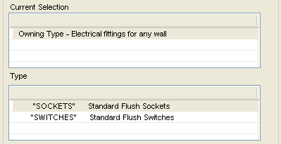
The Owning Type pane of the Wall Fittings window is automatically populated with the types available for selection under the specification.
Click the required type and it is displayed in the Current Selection window.
The Owning Type window automatically changes to the Type window which displays a list of fittings. Click to select one of the items. The selected item is displayed in the Current Selection window and a sub-section item is displayed in the Type window.
Click the next selection in the Type window and the selected sub-section item appears in the Current Selection window.
To modify the properties of the fitting, click Properties, the Modify Properties window is displayed, the name of the CE automatically displayed.
Electrical Fittings: The user can modify the Pline offset, which uses the Pline of a wall to calculate the offset between two design elements that already exist.
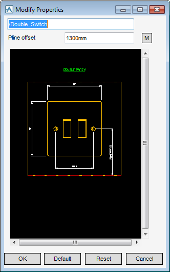
Click Default to return to the default setting.
Click Reset to return to a previous setting.
Click OK to accept the modified properties.
Fire Protection: The user cannot modify any properties.
Standard Windows: The user can modify the Insert from the Modify Properties window, the Inset from the wall face can be set manually or select Measure Inset from the wall face to pick the inset in the 3D view.
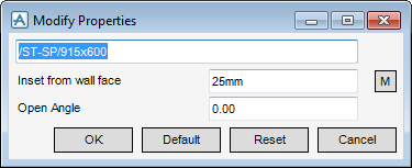
The Open Angle refers to the angle the window is open in the representation of the window in the graphical view.
Click Default to return to the default setting.
Click Reset to return to a previous setting.
Click OK to accept the modified properties.
Standard Door: The user can modify the inset from the wall face, from the Standard Door Modify Properties window. The Inset from the wall face can be set manually or picked in the 3D view, to do this select Measure Inset from the wall face.
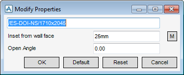
The Open Angle refers to the angle the door is open in the representation of the door in the graphical view.
Click Default to return to the default setting.
Click Reset to return to a previous setting.
Click OK to accept the modified properties.
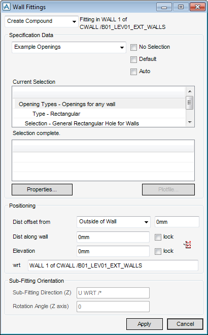
Example Openings: The user can modify the dimensions for the opening. From the Example Opening Modify Properties window for General Rectangular Hole for Walls the X dimension, Y dimension, X offset dimension and Y offset dimension can be set manually or picked in the 3D view. Select the appropriate option.
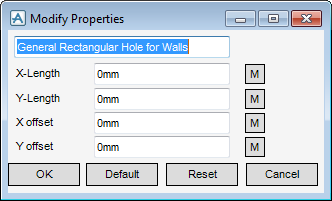
From the Modify Properties window for General Circular Hole for Walls only the diameter can be entered or measured.
Click Default to go back the default setting.
Click Reset to return to a previous setting.
Click OK to accept the modified properties.
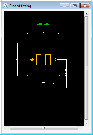
To view a pictorial representation of the wall fitting, from the Wall Fittings window, select Plotfile, the Plotfile window is displayed. The plotfile functionality depends on the type of wall fitting selected:
From the Positioning pane of the Wall Fittings window, the user must specify the distance offset from the outside or inside of the wall.
To position the fitting directly on the wall, click Position fitting to display the Positioning Control toolbar. The user is prompted to ‘Position Fitting (Snap) Snap’.
The Sub-Fitting Orientation pane of the Wall Fittings windows allows the user to orientate a sub-compound fitting relative to its owning compound fitting.
Enter the direction of the Z axis of the fitting in the Sub-Fitting Direction (Z) field.
Enter the rotation of the fitting about its Z axis in the Rotation Angle (Z axis) filed.
To create and insert the fitting, click Apply to insert the wall fitting.
Select the wall where the fittings are to be positioned as the CE in the model explorer or the 3D view. On the WALLS AND FLOORS tab, from the Create group, select Compound Wall Fitting from the drop down list to display the Wall Fittings window. By default, Create Compound is selected.
The procedure to create the compound fitting is the same as for the standard fitting, refer to Create Wall Fittings.
Select the Compound Fitting in the model explorer or 3D view as the CE. On the WALLS AND FLOORS tab, in the Create group, click Wall Sub-Fitting to display the Wall Fitting window. By default, the Create Sub-Compound is selected.