Structural Design
User Guide
Create Panels
On the Plates tab, in the Create group, click Create Panels, select Panel from the drop down list to display the Create Panel window.
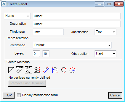
Set the Justification to Bottom (this allows the user to position the bottom face of the panels on the top of their supporting sections).
Set the Thickness, if a panel specification had been set the default thickness would be shown, entering a new value is permitted.
If a Confirm window is displayed, click Yes to override the default thickness value and change it to Unset.
Click No to disregard the entered thickness value and retain the default value.
By default, Representation is set to Predefined: Default. These settings (Levels and Obstruction) affect the way items are shown in 3D views and how they are dealt with when checking for clashes between design items.
Create Methods enables the user to define each vertex the methods used are:
|
|
||
|
|
||
|
|
||
|
|
||
|
|
||
|
|
||
|
|
||
|
|
Click Derive Points From Graphic Picks. The Positioning Control window is displayed and indicates that the user is now in event-driven graphics mode, ready to pick the position of the first vertex.
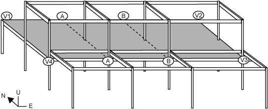
From the Positioning Control window, select Element then Intersect, the user is prompted to ‘Define vertex (Intersection [1]) Snap:’
Pick the column and either of the beams whose intersection coincides with V1 in the diagram. From the Create Methods part of the Create Panel window, ‘No vertices currently defined’ is automatically changed to ‘1 Vertices defined (no Panel created)’. After the definition of this first vertex, Remove Previous Point becomes active. From this the user is able to delete the previous vertex definition.
From the Create Methods part of the Create Panel window, ‘1 Vertices defined (no Panel created)’ is automatically changed to ‘3 Vertices defined (Panel created)’.
As a demonstration, V4 is positioned relative to V3. Click Point Offset From Previous. The Define vertex window is displayed in which the user can specify the required offset.
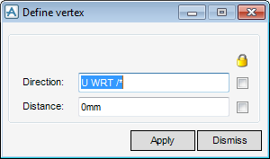
Set the Direction and the Distance, click Apply to create the vertex, or click Dismiss to discard any information and close the Define Vortex window.
The Create Methods part of the Create Panel window, is automatically changed to ‘4 Vertices defined (Panel created)’.
If required, the user can modify the panel vertices immediately, to do this, select the Display modification form check box.
Click OK to complete the panel creation operation. The model explorer now includes one PANEL, one PLOOP and four PAVERT elements (as defined in model explorer).