DRAW
User Guide
Create Pipe Sketches
The Piping Spool data to create a sketch must now be selected. On the Auto tab, in the Create group, click Pipe Sketches to display the Pipe Sketches window.
The Pipe Sketches window contains all the options to search for piping spool data. The user can use any or all of the options.
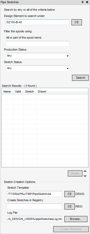
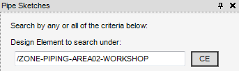
The user can input the name of the design element in the Design Element to search under field.
Alternatively, select the Pipe element in the Model Explorer and click CE on the Piping Sketches window. The selected CE must be a valid element or an error message displays.
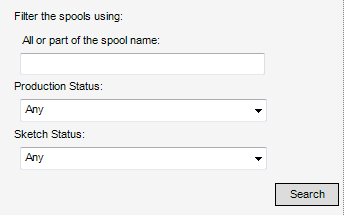
After the Design Element to search under field has been populated, the search criteria for the Pipe Spool data can be customised to search for All or part of the spool name, Production Status and the Sketch Status. The user can populate any of the three fields or all of the three fields.
|
Any - Matches all spools, both validated and not validated.
Valid - Matches only spools valid for production.
Not Valid - Matches only spools not valid for production
|
|
|
Any - Matches all spools, both with and without Piping sketches.
Created - Matches only spools with Piping sketches.
Not Created - Matches only spools without Piping sketches.
|
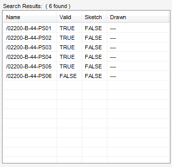
The Name column displays the name of the Pipe Spool.
The Valid column indicates the validation status of the spool, TRUE indicates a validated spool, FALSE indicates a non-validated spool.
The Sketch column indicates the sketch status of the spool. The sketch name displays if a sketch has been created, FALSE displays if a sketch is not created. If the sketch has been created, the sketch creation date displays in the Drawn column.
To create the Piping sketches, select rows on the Search Results part of the Pipe Sketches window to identify which Piping Spools are to be created.
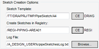
The Sketch Creation Options part of the Piping Sketches window allows the user to define the template to be used for the sketch, a storage area for the created sketch and a log filename.
|
Select the required DRWG element in the Draw Explorer, then click CE. The name of the element is displays in the field.
|
|
|
Select the required REGI element on the Draw Explorer and click CE. The name of the element displays in the field.
|
|
|
To change the file location, click Browse and navigate to the required location to save the log file.
|
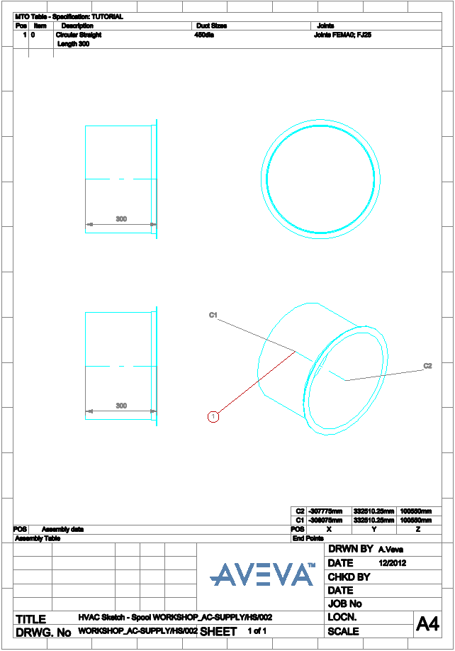
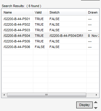
Click Create Sketches to create sketches for the selected rows. The Search Results are refreshed to show the spool sketch has been created and the date it was drawn.
|
Click to view the spool sketch and add it to a working list of sheets for display. Only one sheet can display at a time
|
||
|
|
Click to move the selection up one position in the Search Results, the spool sketch display is updated with the new selection.
|
|
|
|
Click to move the selection down one position in the Search Results, the spool sketch display is updated with the new selection.
|