DRAW
User Guide
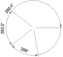
Add Annotation : Dimensions : Add Angular Dimensions
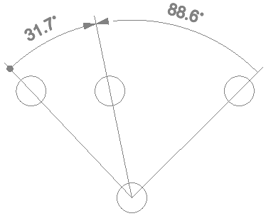
To add angular dimensions, on the Annotate tab, in the Annotate group, click Chained and select the required option from the drop-down list.
Alternatively, on the Home tab, in the Annotate group, click Chained and select the required option from the drop-down list.
The user is prompted to Specify the dimension position point or <Type>
Input values in the dimension fields and press Enter or click to identify the centre point of the annotation.
The user is then prompted to Specify the dimension position point or <Direction>
Input values in the dimension fields and press Enter or click to identify a point to measure from.
The user is then prompted to Specify the dimension point or <Direction>
Input values in the dimension fields and press Enter or click to identify a point to measure to.
The user is then prompted to Specify the dimension line position
Input values in the dimension fields and press Enter or click to identify the position of the dimension line.
The user is then prompted to Specify the dimension point or <Finish>
Input values in the dimension fields and press Enter or click to identify the position of an additional angular dimension.
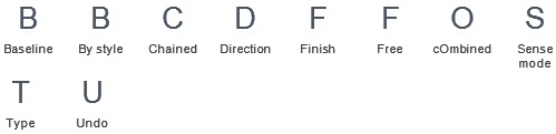
Throughout the angular dimension creation process the user can press ESC to cancel the command. Additional functionality is also available.
 |
|
|
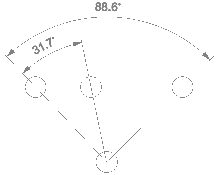
Press the down arrow key and select Baseline to specify the angular dimension type as angular baseline.
|
|
|
Press the down arrow key and select By style to create the angular dimensions using the rotational direction style used to create the previous angular dimension. Refer to Sense Mode for further information.
|
|
|
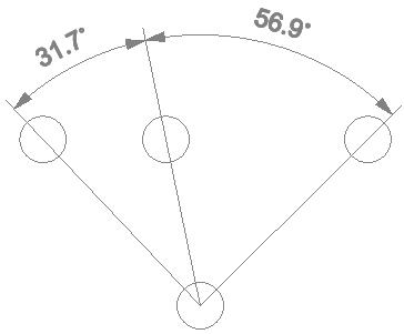
Press the down arrow key and select Chained to specify the angular dimension type as chained.
|
|
|
Press the down arrow key and select Direction to add angular dimensions with a specified direction. Refer to Add Angular Dimensions with Specified Direction for further information.
|
|
|
Press the down arrow key and select Finish to end the command.
|
|
|
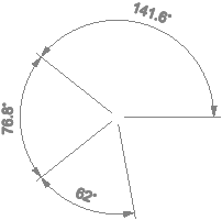
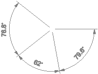
Press the down arrow key and select Free to create the angular dimensions in either a clockwise or anti clockwise rotational direction style. The style is defined by the cursor movement direction used to create the dimension points. Refer to Sense Mode for further information.
|
|
|
Press the down arrow key and select cOmbined to specify the angular dimension type as combined.
|
|
|
Press the down arrow key and select Sense mode to specify the mode of the angular dimension.
|
|
|
Press the down arrow key and select Type to specify the type of angular dimension.
|
|
|
Press the down arrow key and select Undo to undo the last action.
|
|
The sense mode properties of an angular dimension can be modified to alter the display using the Properties window. Refer to Properties for further information.
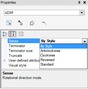
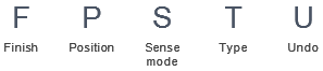
The Sense drop-down list allows the user to define the direction of the angular dimension points.
 |
|
 |
|
 |
|
 |
To add angular dimensions with a specified direction, on the Annotate tab, in the Annotate group, click Chained and select the required option from the drop-down list.
Alternatively, on the Home tab, in the Annotate group, click Chained and select the required option from the drop-down list.
The user is prompted to Specify the dimension position point or <Type>
Input values in the dimension fields and press Enter or click to identify the centre point of the annotation.
The user is then prompted to Specify the dimension point or <Direction>
The user is then prompted to Specify the direction or <Position>
Input values in the dimension fields and press Enter or click to identify the direction of the first dimension line.
The user is then prompted to Specify the vertex direction or <Position>
Input values in the dimension fields and press Enter or click to identify the direction of the second dimension line.
The user is then prompted to Specify the dimension line position
Input values in the dimension fields and press Enter or click to identify the position of the dimension line.
The user is then prompted to Specify the vertex direction or <Finish>
Input values in the dimension fields and press Enter or click to identify the position of an additional angular dimension.
Throughout the angular dimension creation process the user can press ESC to cancel the command. Additional functionality is also available.
 |
|
|
Press the down arrow key and select Finish to end the command.
|
|
|
Press the down arrow key and select Position to add angular dimensions with a specified position. Refer to Add Angular Dimensions for further information.
|
|
|
Press the down arrow key and select Sense mode to specify the mode of the angular dimension.
The user is prompted to Specify sense mode <Free>
|
|
|
Press the down arrow key and select Type to specify the type of angular dimension.
The user is prompted to Select option <Chained>
|
|
|
Press the down arrow key and select Undo to undo the last action.
|
|