Schematic 3D Integrator
User Guide
At any point during the Build or Compare operation there is one schematic object under consideration. This object is referred to as the source. The corresponding design object (if there is one) is referred to as the target. During Compare operations the target will be an actual corresponding 3D object. During Build operations the target represents a "candidate" for a 3D object still to be created.
Create rules are used to create new 3D objects during Build, and to check the existence and type of a matching object during Compare.
Assign rules are used to assign a value to an attribute during Build, and to check the setting of an attribute on the 3D object during Compare. An Assign rule should always be preceded by a Create rule in the same block.
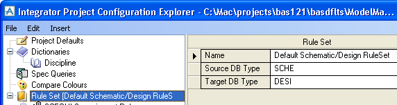
A Rule Set holds all the Rule Groups for a particular pairing of database types. For example, the sample configuration has a default Rule Set for comparing Design database content against Schematic database content.
|
Figure 6:10.
|
You can add Rule Sets for other combinations of database types, e.g. schematic and engineering, for use with Compare/Update.
Create and Assign rules are grouped within a Rule Group. Top level Rule Groups have a Source Type which is the type of object for which they will be applied. Nested Rule Groups have a logical condition that determines when the rules of the Rule Group will be applied. When Rule Groups are nested, the inner rules are only applied if all of the conditions of the owning Rule Groups are met.
The Rule Group name is an alphanumeric string to identify the Rule Group. It is optional and no check is made that names are unique.
The Rule Group condition is a Boolean expression that is evaluated during Build and Compare operations.
For Compare rules, the source and target elements can be referred to in the Rule Group condition. These can be used to refer to attributes or UDAs on the source or target using the "OF" syntax. For example, NAME of source refers to the NAME attribute of the source schematic object. User defined attributes can be used in the same way, for example, :MYATT of source. For Build rules, the target object does not exist and any reference to it may be undefined.
An extended notation allows access to attributes on related elements - owner, previous, next, for example, AREA of OWNER of OWNER of target.
Create rules have a type expression that defines the 3D object type that is to be created (during Build operations), or that is needed to match (during Compare operations). During Build operations the object will be created at the appropriate level in the database hierarchy.
The type expression must evaluate to a legal 3D database object type. This can be an explicit word, e.g. EQUI, or a more complex expression calculated from schematic attribute settings. As in the Rule Group condition, the current source schematic object is referred to as source and its attributes are identified using the "OF" syntax, for example, GTYP of source. More powerful expressions can be created using the syntax described below.
In the situation where more than one 3D object type can be acceptable for comparison purposes, the Create type expression uses the special Variant function. This defines a list of all acceptable matching types, for example, Variant (TEE, OLET, FLAN). Each argument of the Variant function is an expression as defined above. When building, the first type listed in the Variant function will be used.
When the 3D object being created is to be selected from a specification, the questions and answers that inform the selection process are listed in Selector rules owned by the Create rule. Each Selector rule has a Question, e.g. STYP, and a value based on a schematic attribute, e.g. SCSTYP of source.
|
Note:
|
Quotes are not required in selector rules as Integrator will automatically include quotes for text selectors, e.g. a rule with SCSTYP OF source operating on an SCVALV with SCSTYP PTFE-LINED will generate Choose with STYP |PTFE-LINED|.
|

|
Figure 6:11.
|