Pipework Design
User Guide
Pipe Splitting : Modify Branches to Split
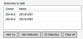
If required, the user can remove individual pipes from the splitting list, right-click over an element to be removed from the Branches to Split list.
The user must select Remove from list from the menu display to remove the selection from the Branches to Split list.
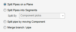
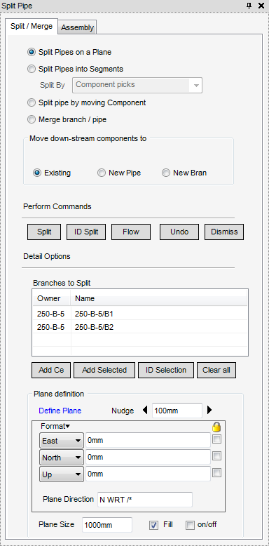
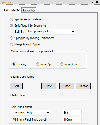
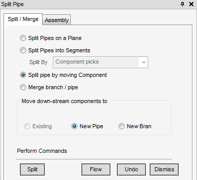
In the Spilt Pipe Options part of the Spilt Pipe window, the user must now choose how the pipe is split, dependent upon which option the user chooses determines the options available from the Spilt Pipe window.
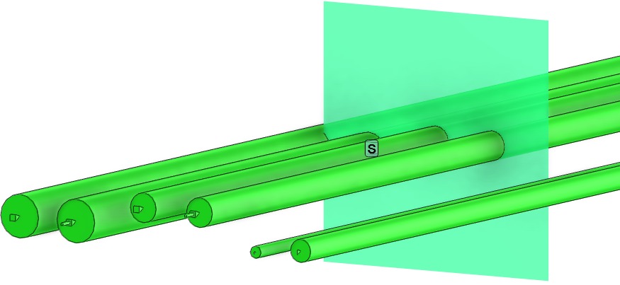
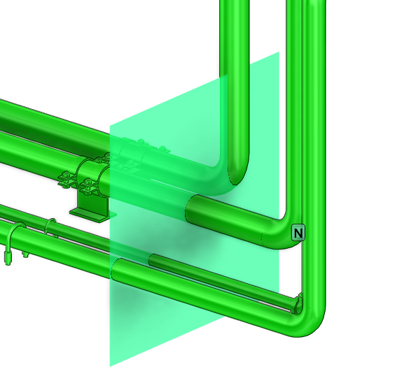
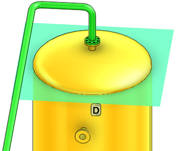
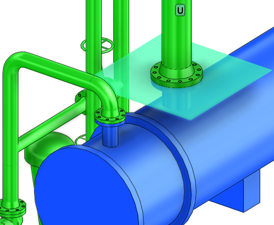
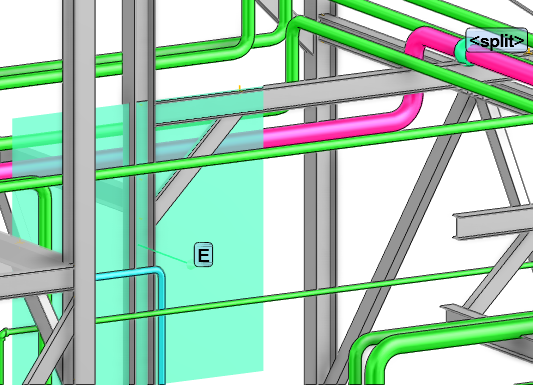
Split Pipes on a Plane - Splits the pipe by inserting an pipe assembly at the point a cutting plane (which is created, defined and positioned by the user) intersects the pipe. Refer to Splitting Pipes with a Plane for further information.
Split Pipes into Segments - Splits the pipe into a number of segments using the dimensions input by the user. The split is defined between two points that are selected by the user (selection of these points can be achieved by the user choosing either the Feature pick or Component pick from the Split By drop-down list). Refer to Split Pipes into Segments for further information.
Split pipe by moving Component - Splits the pipe at the split point and inserts an pipe assembly at that point. The down-stream components in the branch are then be moved. Refer to Component Creation Options for further information.
Select the Split Pipe on a Plane check box to display the relevant options in the Split Pipe window.
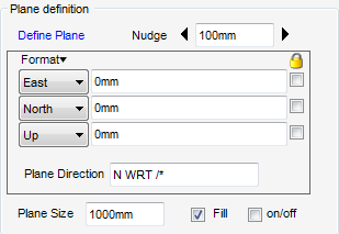
The Plane definition part of the Spilt Pipe window allows the user to define, position and create the cutting plane.
To create and modify the plane, select Define Plane, the user is prompted to select an design element in the 3D graphical view.
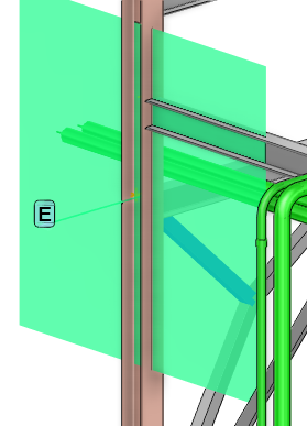
By default the Pipework application displays the plane as a filled representation centred around the defined plane origin. The on/off check box shows or hides the plane, however the on/off check box is automatically selected when the plane is modified.
The user can change how the plane displays, from the Plane definition part of the Split Pipe window. In the Plane Size field, increase the size of the plane and click to clear the Fill check box. The plane display is increased in size and as a wire line representation.
The plane can be positioned explicitly: from the Plane definition part of the Split Pipe window, enter the coordinates in the position fields, if required nudge the plane along with the left and right arrows. The nudge distance is controlled by the nudge increment which is set to 100mm by default. The plane direction can be changed by inputting a valid direction in the Plane Direction field.
When splitting a pipe, the user must define where the components located down stream of the split and inserted assembly are moved to from the Moving down-stream components to part of the Spilt Pipe window.
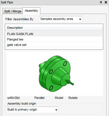
Pipe Assemblies are used as an aid in the pipe splitting process, all of the tasks that a user would carry out that are associated with the use of assemblies as a splitting aid is initiated from a central Split Pipe window with the Assembly tab selected which acts as a task hub.
The user can choose from a list of available assemblies in the Filter Assemblies By part of the Split Pipe window. The assemblies available for selection are those already created in the database, if the user requires an assembly which is not included, refer to Pipe Assemblies for further information or the system administrator.
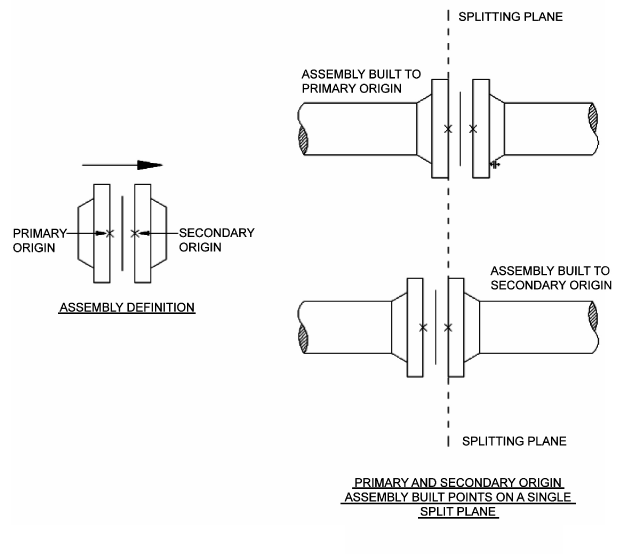
The final option available for plane splitting is the assembly build point; the user must determine whether to build to the primary or secondary origin of the assembly. The user must choose from the Assembly build origin drop-down list.
For more information on Assembly creation and usage, refer to Pipe Assemblies for further information.
The user can also split pipes using a defined plane by directly picking pipes using the mouse cursor. Click ID Split and then use the mouse cursor to select pipes that are split relative to the existing plane. Esc must be pressed to exit this mode.
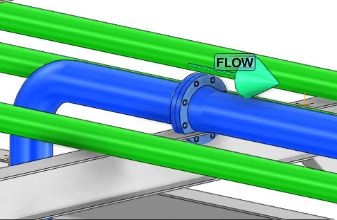
Click Flow to display the direction of flow for the selected pipe.
The user can use Split Pipes in Segments, to split a single branch into segments of a user-defined length between components or features picked by the user in the 3D graphical view (at each split, the choose pipe assembly is inserted). Select Split Pipes into a Segments from the Split Pipe Options on the Spilt Pipe window to display the relevant options.
The user is required to choose the components or selected features adjacent to the pipe to identify the start and stop of the range selection from the Split By drop-down list. Refer to Component Picking and Feature Picking for further information.
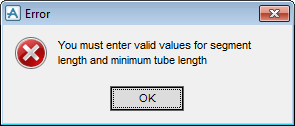
Segment Length: allows the pipes to be split into segments of a particular length between selected components or selected features that are adjacent to the pipe. The split is made by inserting pipe assemblies into the branch. Tube length around bends and elbows is calculated as the centreline length.
Cut Pipe Length: (Used for spool length): allows the pipes to be cut at a particular length between selected components or selected features that are adjacent to the pipe. The cut is made by inserting pipe assemblies into the branch. Tube length around bends and elbows is calculated as the centreline length.
Minimum Final Tube Length - restricts the length of the final tube to the final length value. If the final tube length is below this value, the previous spools are adjusted to make the final length within its tolerance.
The user is required to input the following dimensions to the pipe in the Split Pipe Length part of the Split Pipe window:
|
•
|
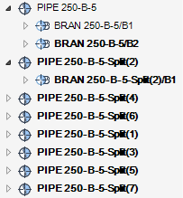
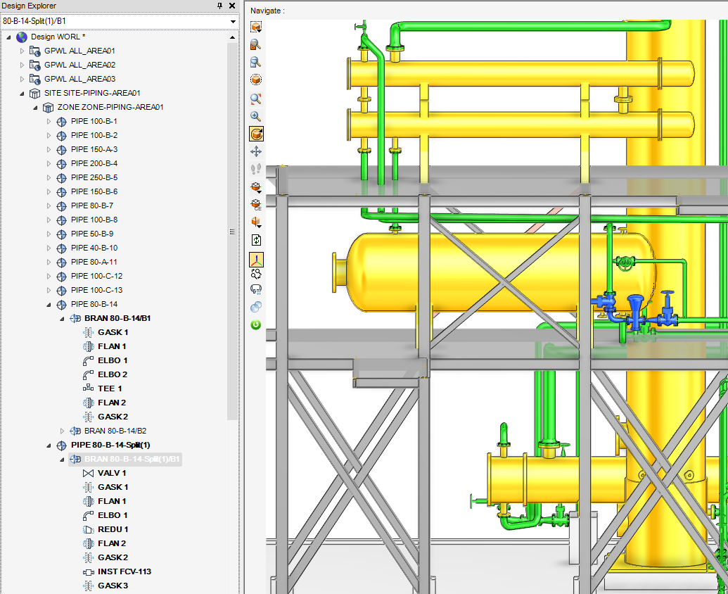
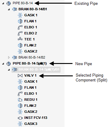
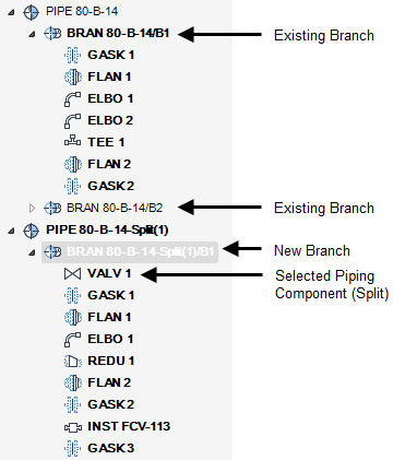
The downstream components at each split may be inserted into the existing branch, a new branch or a new pipe depending on what the user chooses from the Move down-stream components to part of the Spilt Pipe window. If a new branch or pipe is requested, the new items are given a default name based on the pipe name.
The user must select the assemblies to insert into the branch where the split occurs, refer to Pipe Assemblies and Assembly Build Origin for further information. Click Spilt to split selected pipes using components (refer to Component Picking for further information) or selected features adjacent to the pipe (refer to Feature Picking for further information).
To make a split using picked components, the user is prompted to identify start of range selection to select: in the status bar of the 3D graphical view, to start of the range.
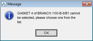
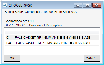
After making the selection, the user is prompted to identify end of range selection to select: in the status bar of the 3D graphical view, to end the range. Once the range has been identified, the software then automatically selects the required generic type component in the current specification. If there is a choice of component and the specification does not have a default, the Message window displays.
Select the component from the CHOOSE window.
Click OK to select the alternative component and close the CHOOSE window or CANCEL to close the CHOOSE window and stop the splitting process.
To make a split using picked features adjacent to the pipe (for example - reference to other parts of the model such as structural steelwork). The user is prompted to identify branch to split in the status bar at the bottom left hand corner of the 3D graphical view. After making the selection, the user is prompted to Pick the starting component, this can be a component or a feature, this is then labelled as the start and the current direction of flow displays. It is possible to split from either end of a pipe.
The user is then prompted to Pick the ending component or <esc> to split branch: after making the selection, the user is prompted to identify section of branch where split will intersect.
Select the component from the CHOOSE window.
Click OK to select the alternative component and close the CHOOSE window or CANCEL to close the CHOOSE window and stop the splitting process.
Click Flow to display the current direction of flow, Undo to discard any changes in the 3D graphical view or Dismiss to close the Split Pipe window.
To make a split by moving a component, select Split pipe by moving component from the Split Pipe Option part of the Split Pipe window. Once the selection has been made, where to move the components down-stream of the split (selection) must be selected. After selecting to where to move down-stream components. Click Split.
The user is prompted to identify branch to split in the status bar at the bottom left hand corner of the 3D graphical view. After making the selection the user is prompted to Pick the piping component.

