Pipework Design
User Guide
Modify Pipework : Slope
Throughout the design process it may be necessary to apply a slope to any existing pipe, and all of the branches within it. To apply a slope to an existing pipe, navigate to an existing pipe and select it as the CE, on the Piping tab, in the Tools group, click Slope Pipe to display the Slope Pipe window.
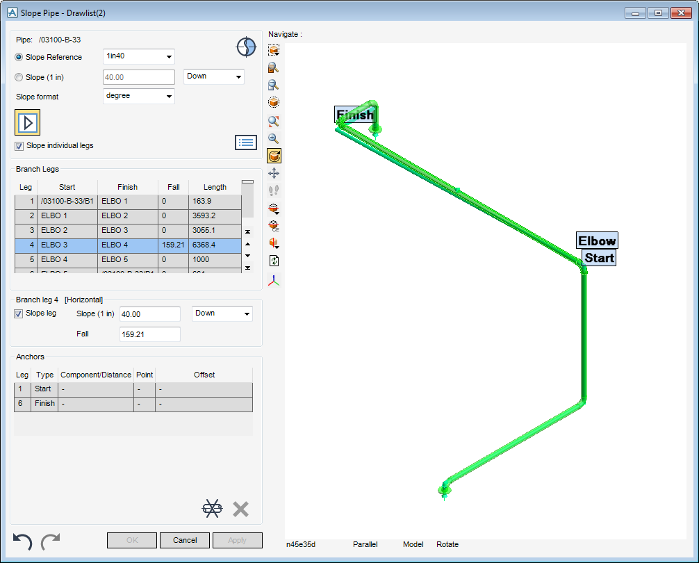
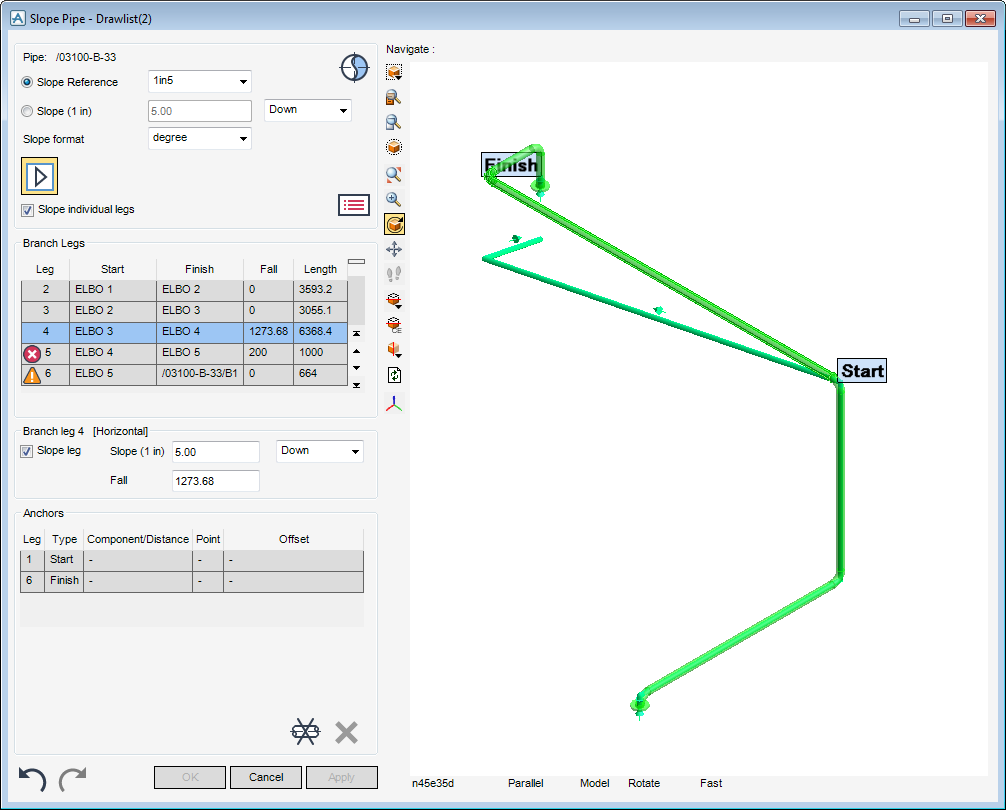
The Slope Pipe window is a dual purpose window which allows the user to view the details of the CE and if required define and apply a slope to any number of branches contained within the pipe element. The window has five panes:
|
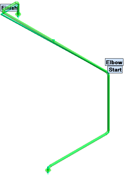
Displays a 3D pictorial representation of the CE, refer to 3D Preview Pane for further information.
|
|
|
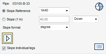
Displays the details on the CE and the slope to be applied to it, refer to Pipe Details for further information.
|
|
|
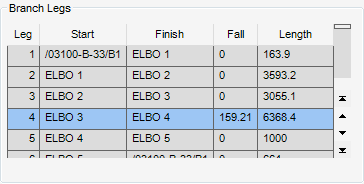
Displays the details for the branch legs which are contained within the CE, refer to Branch Legs for further information.
|
|
|
Allows the user to define the slope for a branch leg, refer to Branch leg for further information.
|
|
|
Displays the details for the anchor points, refer to Anchors for further information.
|
|
Note:
|
The CE is not actually sloped until Apply is selected.
|
The Pipe Details pane of the Slope Pipe window displays the CE, the slope reference, the slope angle, the direction of the slope and the slope format.
Select a slope gradient from the Slope Reference drop-down list to display a preview of the slope in the 3D Preview Pane.
Alternatively, input a slope value into the Slope field and select the slope direction from the slope drop-down list.
Select a slope angle from the Slope Format drop-down list, the defined Slope Format displays in the Slope field.
Click to check the Slope individual legs check box to apply a slope to an individual branch leg. Any previously calculated slope is removed from the 3D Preview Pane display.
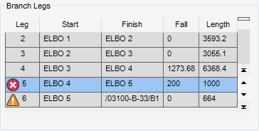
The Branch Legs pane of the Slope Pipe window displays a numbered list of the branches and the components within the current pipe. In addition to the start and finish component for the branch leg, the list includes the length of the leg and the fall of the leg when the slope is applied. Vertical branch legs are not sloped and therefore always have a drop of zero.
During the sloping process the Slope Pipe window lists the components selected for modification which produce a warning or caution. Click Error Messages have been generated by the slope calculation to view the details of the error.
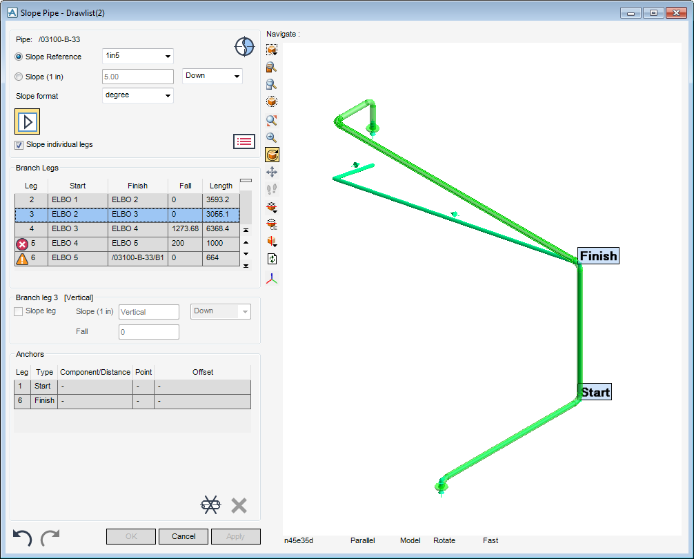
Once an entry has been selected from the list of available legs, the Branch leg pane of the Slope Pipe window is automatically populated with the functionality which allows the user to anchor the selected branch leg and if available modify the slope. The pictorial representation of the CE is automatically labelled.
Select the Slope leg check box to specify that the selected branch leg to be sloped, or select to uncheck the Slope leg check box to force the selected branch leg to be horizontal.
The user must now specify the values for the slope, type the slope directly into the Slope field, the default slope format is defined from the selected Slope format in the Pipe Details pane of the Slope Pipe window. The Fall field is automatically populated with the correct value for the slope. These fields can be populated the other way round if required.
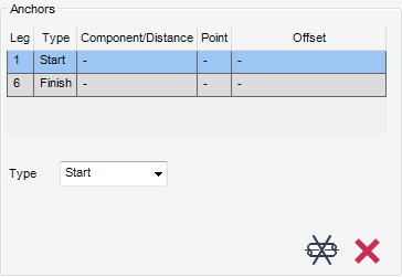
The Anchors pane of the Slope Pipe window displays a numbered list of the branch legs within the current pipe. In addition to the anchor type, the list includes the component/distance for the branch leg, the point and the offset for the anchor.
The anchor type is used to specify the position of anchors. The anchor types available for selection from the Type drop-down list are:
When the Component anchor types is selected, the Anchors pane of the Slope Pipe window is automatically updated with further fields requiring user input.
|
The user is prompted to Pick position (Distance [0]) Snap : in the 3D Preview Pane. Click a position in the 3D Preview Pane to place an anchor.
|
The Component drop-down list identifies the component to which the anchor is to be positioned.
The Point drop-down list determines where on the picked component the anchor is to be positioned, select Top, Centre or Bottom.
To offset each anchor from the previous one by a specified distance relative to a picked position on the picked element., type the distance in the Offset field, then the user must select where to position the anchor relative to a position on the picked element.
When the Position anchor type is selected, the Anchors pane of the Slope Pipe window is automatically updated with further fields requiring user input.
|
The user is prompted to Pick position (Distance [0]) Snap : in the 3D Preview Pane. Click a position in the 3D Preview Pane to place an anchor.
|
The horizontal distance from the start of the leg to the fixed position can be entered in the Distance field.
The Point drop-down list determines where on picked component the anchor is to be positioned, select Top, Centre or Bottom.
To offset each anchor from the previous one by a specified distance relative to a picked position on the picked element. Type the distance in the Offset field, then the user must select where to position the anchor relative to a position on the picked element.
Any inputs into the Slope Pipe window can be reversed:
The addition of offtol attributes to catalogue ppoints means that certain components can have a connection whose direction is allowed to be offset within the limits of the offtol angle. Only one ppoint may have an offtol set. When a ppoint has an offtol set, a new attribute NOMDIR can be used to set the intended arrive/leave direction of the component.
NOMDIR is the equivalent to the use of zero length bends to generate a small angle in a joint and is meant to replace the use of zero length bends where possible.
As the Slope Ref is set at pipe level, all the branches created below it automatically use the same Slope Ref set at pipe level. The user can set an alternative Slope Ref from the Slope Ref drop-down list.
The user must now set the slope of a component’s leave tube by specifying the required rate of fall or slope angle. Applies only to a component which involves a change of direction (such as an elbow). As a result, the Slope window only displays where an offset can be applied, for example, the component has an offset on the ppoint.
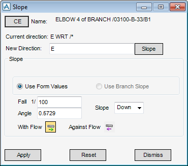
By default the currently selected element is named in the Slope window along with its current direction, current slope attributes and direction of flow.
To change the CE, in the Model Explorer, select the required element from the design database, then click CE.
To apply the current slope to the leave direction of the CE, click Slope. Alternatively the user can type the required direction into the New Direction field.
If the branch has not had a slope reference set, the Slope pane of the Slope window is populated with slope attributes and Use Form Values is selected.
The slope of 1/100 and angle 0.5729 displays by default, this is the slope applied to the branch, but the user can modify the slope applied to the branch using the Fall, Angle and Direction functionality available from the Slope window.
The user can set the slope of the branch as a rate of fall or as an angle, click Fall or Angle input the rate of fall or angle of the pipe.
The user is required to choose the direction of the slope from the Slope drop-down list.
Select Against Flow to place the system into backwards mode.
Select With Flow to place the system into forwards mode.
To set the direction, click Apply to change the slope, Reset to discard any inputs or Dismiss to close the Slope window.
The new direction is now set by setting the NOMDIR attribute of the flange. NOMDIR is now the leave direction of the flange.
If the branch has a slope reference set, Use Branch Slope is selected and the Fall or Angle attributes are displayed as the slope reference and are unavailable for modification.
The user is required to choose the direction of the slope from the Slope drop-down list.
Select Against Flow to place the system into backwards mode. Or select With Flow to place the system into forwards mode.
To set the direction, click Apply to change the slope, Reset to discard any inputs or Dismiss to close the Slope window.
The new direction is now set by setting the NOMDIR attribute of the flange. NOMDIR is now the leave direction of the flange.

